Light sensor replacement, Temperature sensor replacement – Daktronics Galaxy AF-3500 Series Double Face User Manual
Page 28
24
Parts Replacement
2. Remove the module directly in front of the appropriate power supply.
3. Disconnect the Mate-n-Lok
®
connectors from the power source as well as those going to the modules.
Be sure to label each connector so that it can be properly reconnected.
4. Loosen the screw holding the power supply bracket to the cabinet upright and lift it off the hooks.
5. Carefully pull the power supply out of the cabinet.
6. Move the new power supply into place and tighten the screw on the support bracket.
7. Reconnect all the Mate-n-Lok
®
plugs so that each module will receive power.
Light Sensor Replacement
Tools required:
3
/
16
" nut driver, Phillips screwdriver
The light sensor assembly is mounted inside the bottom-left edge of the
cabinet. Refer to
Figure 11 for location.
If the light sensor fails, only the circuit board needs to be replaced.
Remove the bottom-left module on the display to access the light sensor.
To replace a light sensor circuit board as shown in
these steps:
1. Remove the screws that hold the light sensor to the cabinet.
2. Remove the #4-40 nuts securing the circuit board to the plate.
3. Remove the standoffs and attachment screws from the board.
4. Disconnect the four electrical wires on the sensor by unscrewing
each screw that holds a wire in place. Note the order the wires
are connected so they can be reconnected in the same locations
on the replacement.
5. The light sensor plug on the controller does not need to be detached.
6. Reattach the new circuit board, following these steps in reverse.
Note: Align the new circuit board so that the lens lines up with the 1/2”circular opening in the bottom left
edge of the display when the assembly is in place.
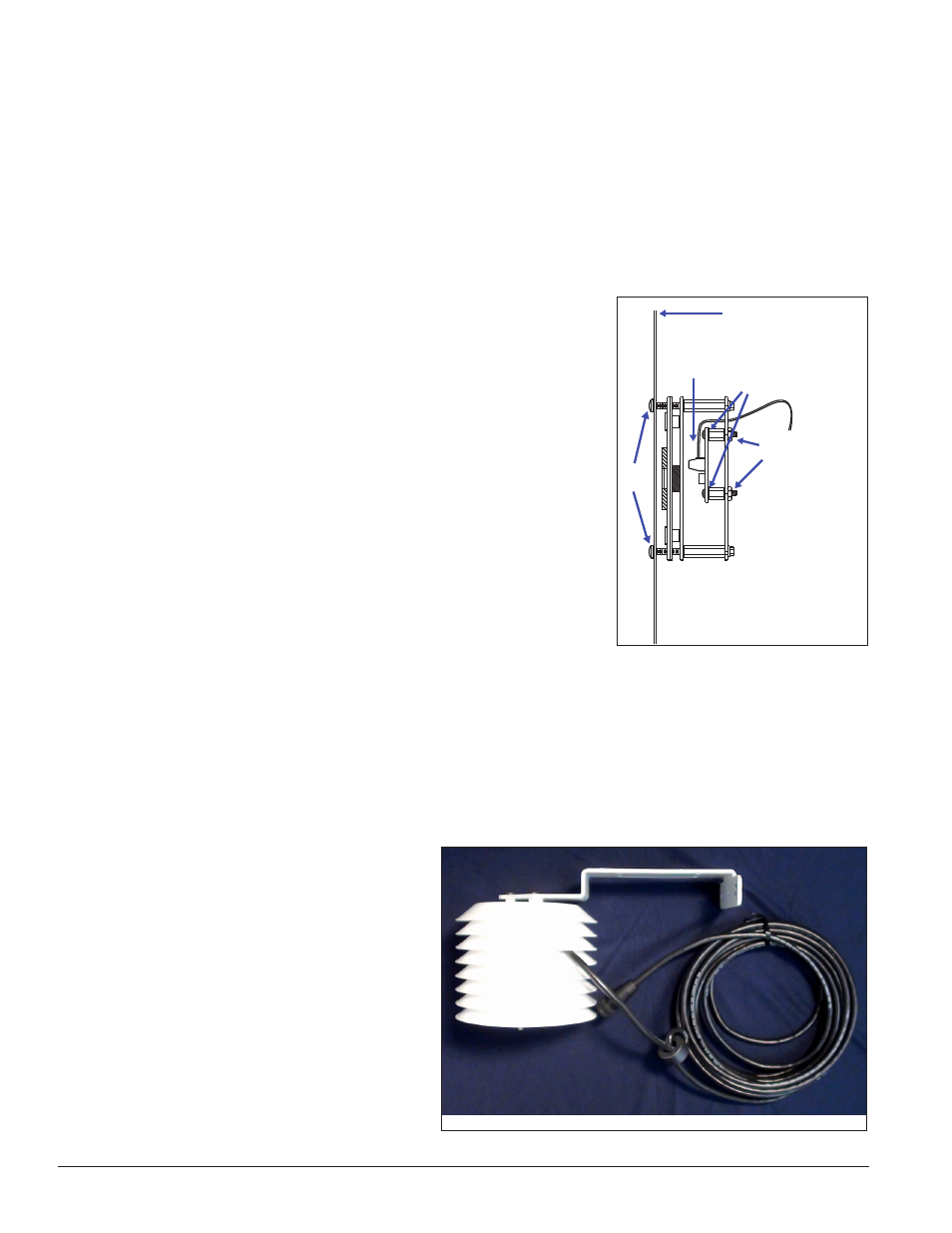
Temperature Sensor Replacement
Tools required: Phillips screwdriver
If the temperature sensor malfunctions,
replace the entire unit.
The temperature sensor enclosure, shown in
Figure 24, is composed of eight plastic disks,
a metal mounting bracket, and a 25-foot
weather-resistant cable.
In most cases, the enclosure is mounted using
four screws. The cable plugs into quick-
connect jack J31 on the back of the display.
1
2
3
4
Front Panel of Display
Figure 23: Light Sensor Assembly
Figure 24: Temperature Sensor and Mounting Bracket