2 internal display access, 3 ventilation system/fans, Internal display access – Daktronics Galaxy AF-3500 Series Double Face User Manual
Page 18: Ventilation system/fans
14 Maintenance
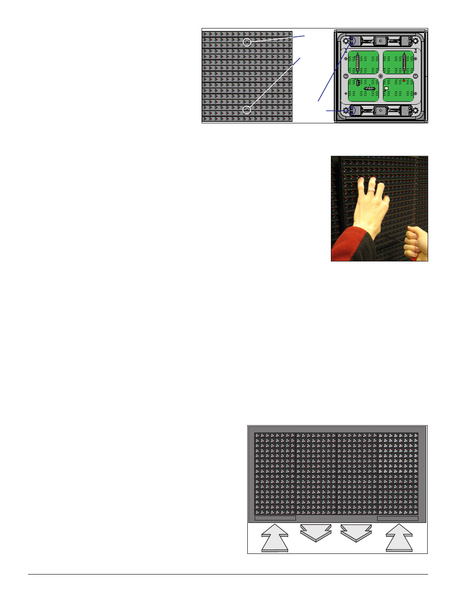
6.2 Internal Display Access
Access the display interior to perform
maintenance or troubleshooting by
removing the front modules.
1. Disconnect power to the display.
2. Locate the latch access fasteners
on the module as shown in
Figure 13. One is centered near
the top and one is centered near
the bottom.
3. With a
1
/
8
" hex wrench, turn the latch access fasteners a quarter turn
counter-clockwise, as shown in
Figure 14. Gently pull the module
far enough forward to reach behind it and disconnect the power and
ribbon cables.
4. Disconnect the two ribbon cables from the module by spreading the
tabs on the sides and then lifting the cable head from the jack. Note the
cable connections so they can be reconnected correctly.
5. Unplug the power cables by squeezing the tabs on the sides of the plug
head and pulling out.
6. When ready to reinstall the module, reconnect the cables, making sure
that the tabs are tightly pushed against the cable head. Carefully push
the ribbon wires back into the cabinet so they are clear of the module edges.
7. Place the module into its proper location, checking that the weather stripping is in place. Latch the
module at both the top and bottom locations by turning the hex wrench clockwise a quarter turn.
Notes:
• Weather stripping on the back edge of the module must be intact and in good condition to prevent
water from entering the display.
• Module latches must be fully engaged to create a watertight seal around the edge of the module. The
module seats firmly against the display when the latches are fully engaged.
6.3 Ventilation System/Fans
AF-3500 series displays are equipped with ventilation
systems to help keep the internal electrical components
at operable temperatures. Intake fans bring air into the
display through vents situated on the bottom of Face
A. Exhaust then leaves the display through adjacent
vents along the bottom of Face B.
example of the display’s airflow.
Note: Air vents are located behind a false face and
cannot be readily seen.
A smaller fan is also located on the display controller
enclosure cover which should always be running.
1/8 hex
wrench for
access
fasteners
Module Latch
Assembly
Figure 13: Module Latch Locations (20 mm)
Figure 14: Removing a Module
DAKTRONICS
Galaxy
Figure 15: Ventilation Airflow