Controller address setting, Memory storage card, Power supply replacement – Daktronics Galaxy AF-3500 Series Double Face User Manual
Page 27: And figure 21, Parts replacement 23, Figure 21: rotary address switches, Figure 22: power supply
Parts Replacement
23
Controller Address Setting
The rotary switches set the hardware address which the software uses
to identify each particular display. Each controller in a network needs a
unique address.
To set the rotary address switches, rotate them until the arrow points to
the desired number, as shown in
Figure 21. The display’s power must be
turned off and then turned back on to activate the test mode or to change
an address.
Notes:
• Setting both rotary switches to address 0 will activate Test Mode.
Turn the display’s power off and back on to activate testing.
• After testing, reset the rotary switches to an address other than 0/0
and repower the controller (the software will not recognize an address of 0).
Memory Storage Card
Do not remove the memory storage card with power connected to the controller or critical damage will result.
The controller in the Galaxy display contains a 2 GB memory storage card. This card stores the configurations,
messages and schedules, and fonts created by the control software. The memory storage card can be moved
if a controller needs to be replaced or if the information stored on it needs to be used on another display.
The information on the card will automatically be recognized and available for use by the display, thus
eliminating the need to reconfigure a display.
To remove the memory storage card, disconnect power and then gently push in on the edge of the card. The
card will spring out of its location on the controller.
To install a memory storage card, slide it into the slot on the side of the controller. Push it gently in until a
click is felt. The card should now be held firmly in the slot.
Note: The memory storage card is specifically designed to work with the Galaxy controller. Do not attempt
to reprogram or move files by inserting this card in a computer or other device. The card will then no longer
function correctly in the controller.
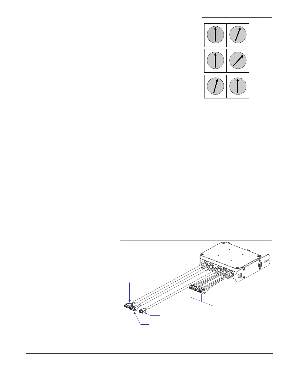
Power Supply Replacement
Tool required: Phillips screwdriver
Galaxy displays use 135-watt
power supplies that run up to four
modules (eight modules in 34 mm
monochrome displays).
Each module is connected to a
wire harness on the power supply
by a Mate-n-Lok
®
cable. Refer to
Figure 22 for an example.
Complete the following steps to
replace a power supply:
1. Turn off power to the
display.
Upper
Lower
Address 1
0 – 1
Address 2
0 – 2
0 1 2
3
4
5
6 7
8
9
A
B
C
D
E
F
0 1 2
3
4
5
6 7
8
9
A
B
C
D
E
F
0 1 2
3
4
5
6 7
8
9
A
B
C
D
E
F
0 1 2
3
4
5
6 7
8
9
A
B
C
D
E
F
0 1 2
3
4
5
6 7
8
9
A
B
C
D
E
F
0 1 2
3
4
5
6 7
8
9
A
B
C
D
E
F
Address 16
1 – 0
Figure 21: Rotary Address Switches
DC Outputs (To Modules)
AC Input
(From Power
Source)
AC Output (To Next Power Supply)
V Adjust (To Initial Module)
Figure 22: Power Supply