Section 7: diagnostics and troubleshooting, 1 controller diagnostics, 2 troubleshooting display problems – Daktronics Galaxy AF-3500 Series Double Face User Manual
Page 21: Section 7, Diagnostics and troubleshooting, Controller diagnostics, Troubleshooting display problems
Diagnostics and Troubleshooting
17
Section 7: Diagnostics and Troubleshooting
Important Notes: Disconnect power when servicing the display. Only qualified service personnel should service
internal electronic components.
7.1 Controller Diagnostics
The controller is the “brains” of the display, receiving
communication from the computer and then sending
information to the modules. The controller is
located in the lower-left area of displays as shown
in
Figure 10. LEDs on the controller show whether
power and communication signals are working
properly.
To access the interior of the display, refer to
Section
6.2 for instructions and illustrations. Remember to
disconnect power to the display before accessing the
interior. However, once the modules are removed and
wires are found to be safe, power can be turned back
on to view the diagnostic LEDs.
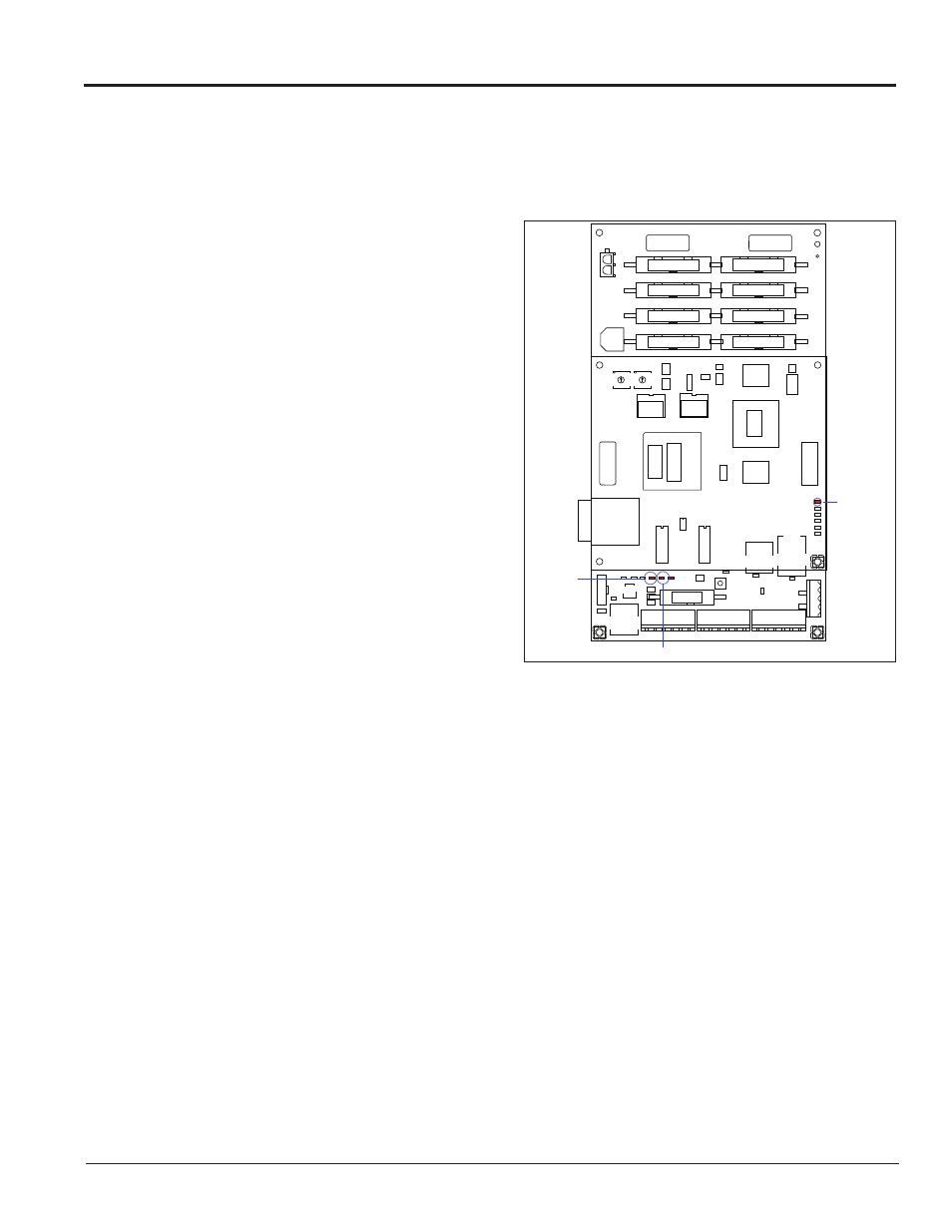
A Galaxy controller is illustrated in
Figure 17 with
essential diagnostic LEDs labeled:
• The DS4 LED signifies the controller’s
operational status. This LED flashes about
once per second to indicate the controller is
functioning properly.
• The DS3 LED signals the controller’s
transmission status. This LED flashes only
when transmitting information to the modules.
• The DS2 LED displays the controller’s receiving status. This LED flashes only when receiving
information from the control computer.
7.2 Troubleshooting Display Problems
This section contains some symptoms that may be encountered with displays. This list does not include every
symptom or solution but does represent common situations and simple steps to resolve them.
Troubleshooting may require removal and replacement of modules. Refer to
Section 6.2 for more
information. When replacing modules, make sure power and signal cables are reconnected correctly and the
latches are tightly closed.
ADDRESS
UPPER
LOWER
0
8
0
8
DS3
Transmit
DS4 Run
DS2 Receive
Figure 17: Controller Diagnostics