For displays with internal power termination, 7 power routing in the display, Power routing in the display – Daktronics Galaxy AF-3500 Series Double Face User Manual
Page 12: 8power installation
8
Power Installation
For Displays With Internal Power Termination
Terminating single-phase power to the internal power
termination panel:
1. Open the display as explained in Section 6 and locate
the power termination panel.
2. Route the cable through conduit to the back of the
display. Use the
3
/
4
" knockout for access, being
careful not to damage internal components.
3. Connect the neutral wire to the neutral lug and the
live wires to the Line 1 and Line 2 lugs.
4. The ground wire connects to the grounding bus bar.
Figure 9 for an example.
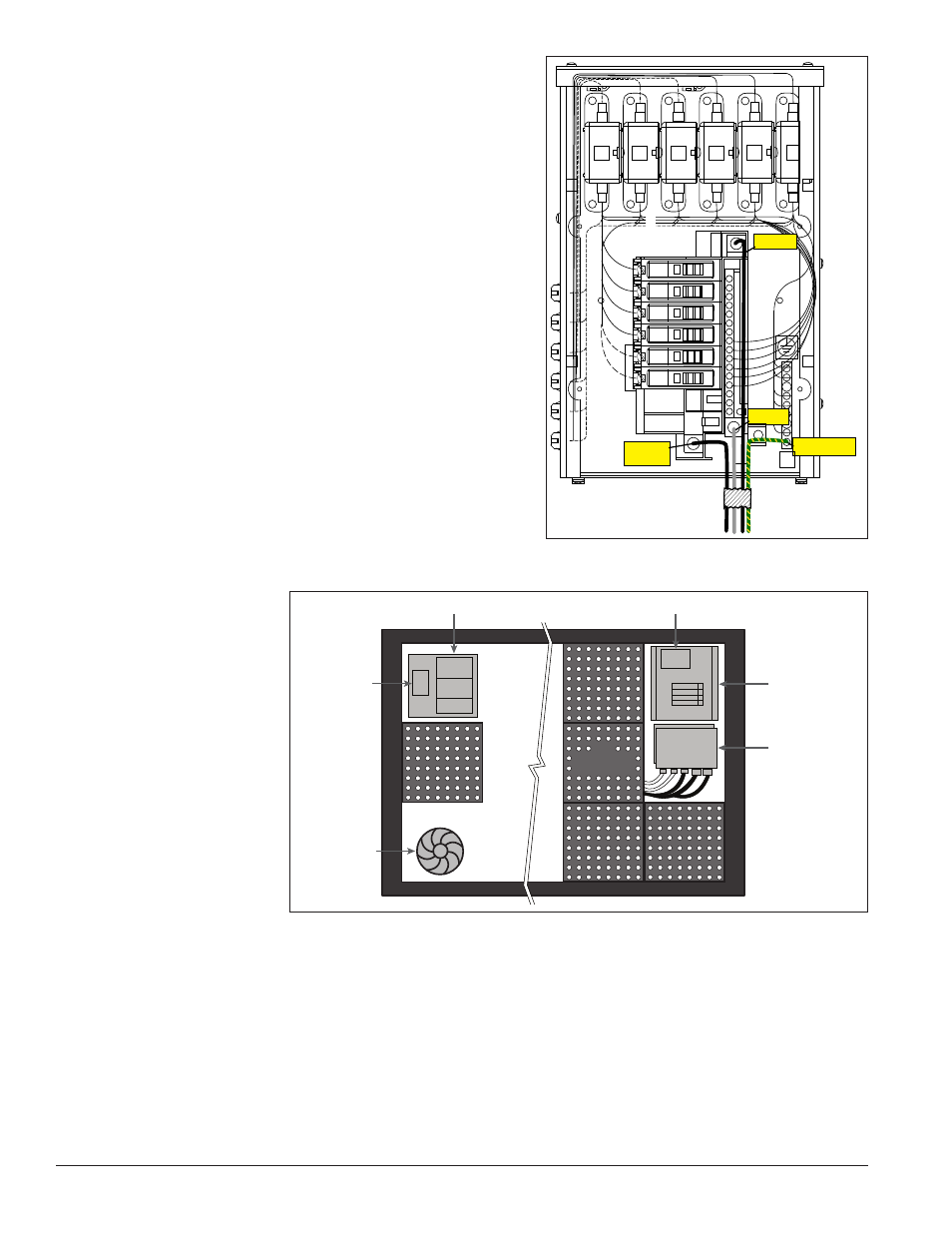
3.7 Power Routing in the Display
A general power routing, as shown in
Figure 10, can be
summarized as follows:
1. Power terminates internally to the power termination
panel (either directly or via the side-mounted J box).
2. Power routes through the circuit breaker(s) in the
power termination panel.
3. Power is routed
through filters
to the power
supplies which
provide power
to the modules.
4. Power travels
through the
transformer
which steps
down power to
the appropriate
voltage for the
controller.
5. Power is also
routed through
a filter to the
thermostat and the fans. The fans are activated by either the relay or thermostat.
Note: Power supplies are set to the proper voltage by the modules.
15
15
15
15
15
15
GRN
WHT
BLK
GRN
Z1
Z2
Z3
Z4
Z5
Z6
LINE 1
NEUT.
E41
LINE 2
GROUND
Figure 9: Single-phase 6-breaker Domestic Panel
3
Transformer
4
4
3
Modules
5
3
1
2
5
Power
Term
Panel
Z-filter
Power Supplies
Controller
Fans
Figure 10: Power Flow Summary