Important points about grounding, 6 power connection, Power connection – Daktronics Galaxy AF-3500 Series Double Face User Manual
Page 11
Power Installation
7
Important Points About Grounding
• Resistance to ground 10 ohms or less: This is required by Daktronics for proper display performance.
If the resistance to ground is higher than 10 ohms, install additional grounding electrodes to reduce the
resistance. The grounding electrode should be installed within 25' (7.6 m) of the base of the display and
must be connected to the ground lug on the back of the display. Refer to
• Follow local and national codes: The material of an earth-ground electrode differs from region to region
and for conditions present at the site. Consult any local and national electrical codes that may apply.
• Support structure cannot be used as an earth-ground electrode: Daktronics does not recommend using
the support structure as an earth-ground electrode; concrete, primer, corrosion, and other factors make
the support structure a poor ground.
Note: The support structure may be used as an earth-ground electrode only if designed to do so. A qualified
inspector must approve the support structure and grounding methods.
• One grounding electrode for each display face: The grounding electrode is typically one grounding rod
for each display face. Other grounding electrodes as described in any local and national electrical codes
may be used.
3.6 Power Connection
Power is most often terminated externally to the J-box on
displays. However, larger displays require power to be
terminated internally in the Power Termination Panel.
For Displays With an External Power
Termination J-box
Terminating hot, neutral, and ground wires at the J-box:
1. Route the power cable through conduit to the rear of
the display and into the power termination J-box (the
J-box contains
3
/
4
" threaded conduit fittings).
2. The J-box contains two or three wires plus a ground
coming from the interior of the display. These wires
are pre-terminated to the power termination panel
inside the display.
3. Inside the external J-box, connect the power wires to
the wires coming from the display interior using wire
nuts. Refer to
Figure 7 for 120 VAC and Figure 8 for
120/240 VAC.
Note: The following colors are used for the pre-terminated
wires:
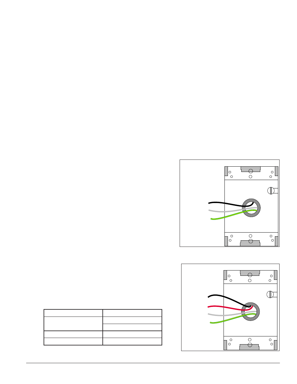
120 V Termination
(Box with Cover Removed)
Wiring from power termination
panel inside display
Line 1 – Black
Neutral – White
Ground – Green/Yellow
Figure 7: 120 V J-box Termination
120/240 VAC Termination
(Box with Cover Removed)
Wiring from power termination
panel inside display
Line 1 – Black
Line 2 – Red
Neutral – White
Ground –
Green/Yellow
Figure 8: 120/240 V J-box Termination
120 VAC
120/240 VAC
•
Line 1 – Black
•
Line 1 – Black
•
Line 2 – Red
•
Neutral – White
•
Neutral – White
•
Ground – Green/Yellow •
Ground – Green/Yellow