5 power connection, Power connection -4 – Daktronics Galaxy AF-3200 34 mm User Manual
Page 15
resistance. The grounding electrode should be installed within 25 feet of the
base of the display. The grounding electrode must be connected to the ground
lug on the back of the display.
3.5 Power Connection
Two options are possible for terminating power to the display:
Option 1: Connecting to the power termination enclosure on the display back.
Option 2: Connecting directly to the power termination panel inside the display.
Installation instructions for both are provided in this section.
Option 1: Terminating hot, neutral, and ground wires at the enclosure
1. Route the power cable through conduit to the rear of the display and into the
power termination enclosure.
2. The power termination enclosure will contain two or three wires plus a
ground coming from the interior of the display. These wires are pre-
terminated to the power termination panel inside the display.
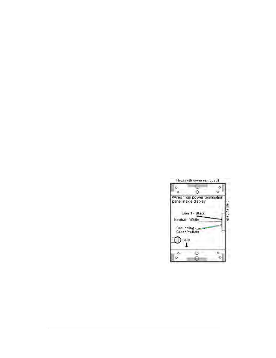
3. Inside the external power termination J-box, connect the power wires to the
wires coming from the display interior using wire nuts. Refer to Figure 8
for a diagram.
Note: The following colors are used for the pre-terminated wires:
• Line 1 – Black (Brown – 240V)
Figure 8: Power Termination Wiring
• Line 2 – Red (only on three wire installations
– 120/240V)
• Neutral - White (Blue – 240)
• Grounding Conductor – (Green-Yellow)
Power Installation
3-4