3cascadingandethernetconnectiondiagram, 2wirelessone-wayreceiver:cr-rfa, 1howtouse – CREATOR CR-PGMIII User Manual
Page 20: 2 wireless one-way receiver: cr-rfa, 13 pgmⅢ programmable ethernet control system
CREATOR CHINA 2011-03
WWW.CREATOR1997.COM
13
PGMⅢ Programmable Ethernet Control System
3.1.3
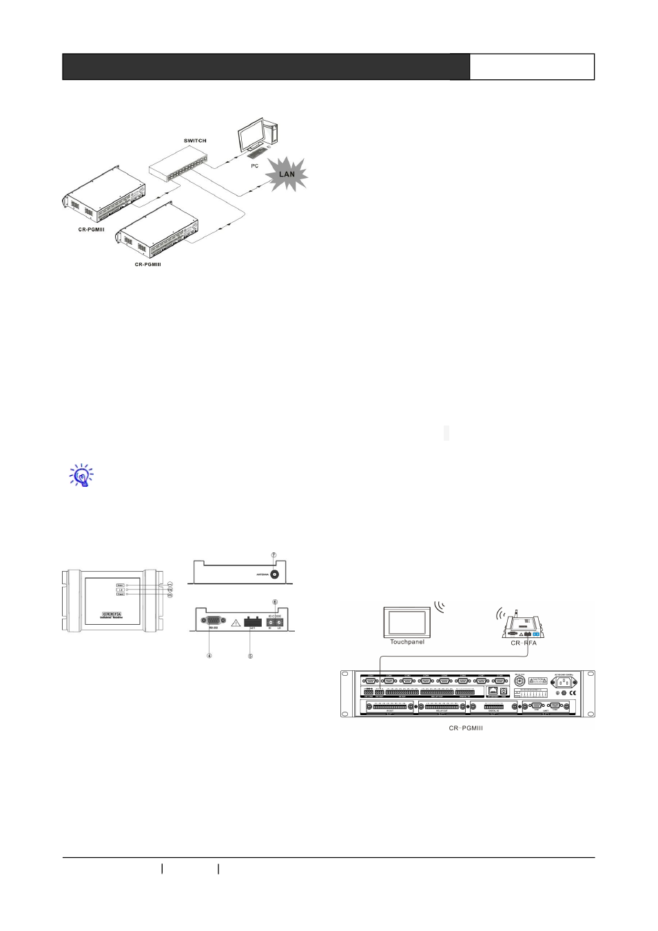
Cascading
and
Ethernet
Connection Diagram
3.2 Wireless One-way Receiver:
CR-RFA
The CR-RFA wireless ( RF ) one-way receiver
provides the connection between the controllers
and the one-way programmable touch panels,
which works on 433MHz, is of one-way
communication.
The ID CODE setting has to be the same as
corresponding settings on the controllers, or, they
will not be able to communicate.
Interfaces:
1 ) POWER——Power indicator: will be ON
when power supply has been connected
2) ID——ID indicator
When the connection is between the CR-RFA and
the controller, the ID indicator on the receiver and
the NET ID on the controller will be ON.
3) SIGNAL——Communication indicator
When the CR-RFA receives the wireless signal
from the touch panel, the indicator will be
flashing.
4) RS-232—— Serial Port
Reserved port for the CR-RFA’s extension
functions.
5) NET——4 bit network interface
It is the communication interface between the
CR-RFA and the controller, connecting to the
CR-NET interface on the controller.
6) ID CODE——Network ID
To set the CR-RFA’s network ID. Please be noted
that the Network ID has to be same as the
CR-RFA’s ID in the program written by the Control
System Builder Software.
7) ANTENNA—— Spiral antenna
3.2.1 How to use
Generally it is used while the wireless controlling
distance is relatively short (within the same room,
for example). Besides the remote control, the
special PC Serial Port software can be used to
enable sending out continuous RF control
command from the PC.
Connection: