Comtech EF Data DD2401 User Manual
Page 71
DD2401 Satellite Demodulator
Electrical Interfaces
MN-DD2401 - Rev. G
5-
3
5.4 SERIAL CONTROL & AGC Monitor (J3)
The Serial Control Interface Port (J3) is used for remote monitor and control utilizing Radyne's
RLLP Protocol. It offers a direct single connection to the individual demodulator. It is a Female
25-Pin D-Sub Connector supporting RS-232 or RS-485. Refer to Table 5-2A for Remote
interface pinouts and Table 5-2B for AGC Monitor pinouts.
For multi-drop communications, it is recommended that the J5 be used. The J5 connector multi-
drops all Remote ports connections allowing the user to connect to a single port. Refer to section
5.6 for additional information.
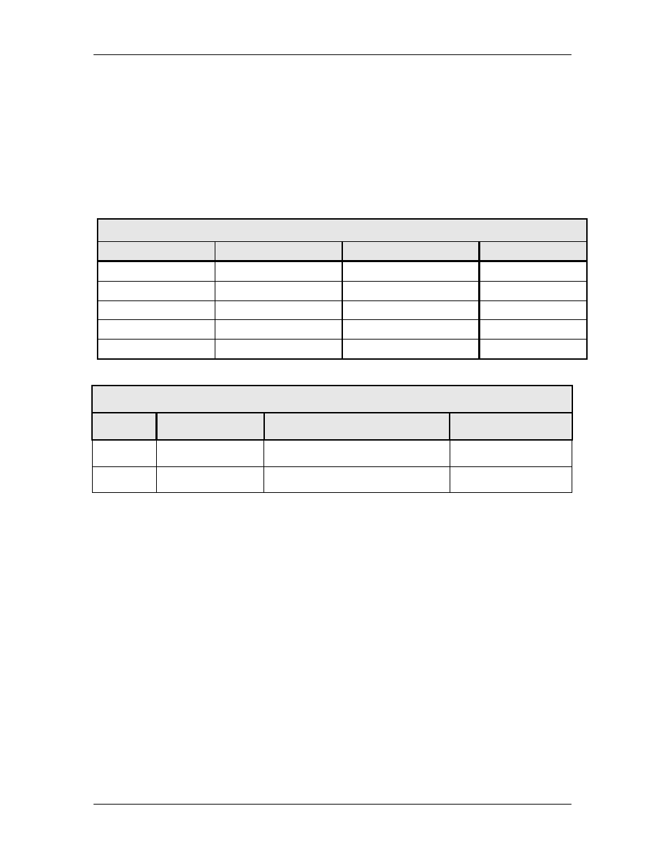
Table 5-2A. Serial Control Interface Port (J3) - 25-Pin ‘D’ Female
Pin No.
RS-232 Signal Name
RS-485 Signal Name
Direction
9
TXD
TXD-B
Output
10
TXD-A
Output
16
RXD
RXD-B
Input
3
RXD-A
Input
7
GND
GND
---
Table 5-2B. AGC Monitor (J3) - 25-Pin ‘D’ Female
Pin #
Signal
Description
Direction
5
AGC
AGC Out
Output
7
GND
Ground
---
5.5 RX IN
5.5.1 L-Band (J4)
The Receive Input (J4) is the 950 – 1750 MHz Demodulator IF Input. It is a SMA (1) Connector.