Comtech EF Data DD2401 User Manual
Page 70
Electrical Interfaces
DD2401 Satellite Demodulator
5-
2
MN-DD2401 - Rev. G
5.2 Terrestrial Data & Terminal Control Interface (J1)
The J1 Interface supports RS-422 synchrounous Terrestrial Data and RS-232 Remote Terminal
Communications. It is a Female 25-Pin D-Sub Connector. Refer to Table 5-1 for connector
pinouts and Section 4.2 terminal setup and menu descriptions.
Radyne supplies an interfacing Y cables that standardize the terrestrial interface to RS-530 or
RS-449 connection. The Y cable includes a DB 9 connector for Terminal communications that
allows the user to connect to a computer or terminal interface.
• RS530 Y cable is CAR5941
• RS449 Y cable is CA/4263
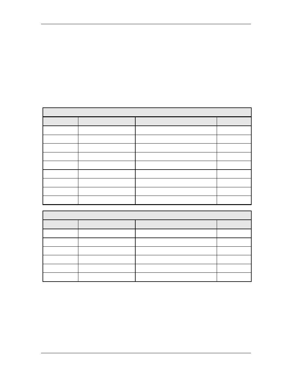
Table 5-1A. Terrestrial Data Interface Port (J1) - 25-Pin ‘D’ Female
Pin No.
Signal Name
Description
Direction
1
Shield
---
3
RXD-A
Receive Data
Output
6
DSR
Data Set Ready (Always True)
Output
7
GND
---
8
CD-A
Demod is Phase Locked
Output
9
RXC-B
Receive Clock
Output
10
CD-B
Demod is Phase Locked
Output
16
RXD-B
Receive Data
Output
17
RXC-A
Receive Clock
Output
Table 5-1B. Terminal Interface Port (J1) - 25-Pin ‘D’ Female
Pin No.
Signal Name
Description
Direction
18
TX-232
RS-232 (Terminal)
Input
20
Unused
---
21
RX-232
RS-232 (Terminal)
Output
22
Unused
---
23
GND
---
25
Unused
---
5.3 EXT REF
The External Reference Input (J2) is supplied to allow the customer to phase-lock the
demodulator’s internal oscillator to an external reference. All internally generated frequencies
within the modem will attain the stability of the applied external reference.
This female BNC Connector accepts a 1.5 – 5 Vp-
p @ 50Ω. The frequency range of the external
reference is 1 – 10 MHz in 8 kHz steps.