I/o schematic diagram – D-Link DCS-1000 User Manual
Page 71
70
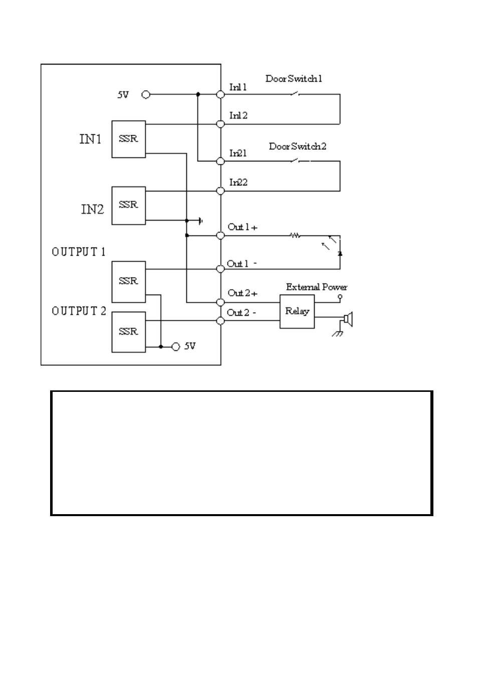
I/O Schematic Diagram
Note:
Through the Web Configuration in the Trigger section, you must first enable
the trigger function. Please refer to the Web Configuration section for detailed
information.
Warning
1. When connecting a device to the Input connector, the device must be
a passive component without voltage and electrical current.
2. When connecting other devices through the Output connector, please
make sure the maximum current of DC 5V, 100mA is strictly
observed.
3. Any failure of the above two points might cause serious
damage to
the camera.