Physical description, Front panel – D-Link DCS-1000 User Manual
Page 6
5
Connection to External Devices
Supporting auxiliary Input/Output Connector, you can connect DCS-1000 to a
variety of external devices such as IR-sensors, switches and alarm relays. One
can combine with programmable alarming facilities to develop a variety of
security applications that are triggered on alarm-based events. DCS-1000
provides up to two in/out external devices for connectivity.
Broad Range of Applications
With today’s high-speed Internet services, DCS-1000 can provide the ideal
solution for live video images over the Intranet and Internet for remote
monitoring. DCS-1000 allows remote access from a web browser for live
image viewing and allows administrator to manage can control DCS-1000
anywhere and any time in the world. Apply DCS-1000 to monitor various
objects and places such as homes, offices, banks, hospitals, child-care centers,
amusement parks and other varieties of industrial and public monitoring.
DCS-1000 can also be used for intruder detection, capture still images and
video images for archiving and many more applications.
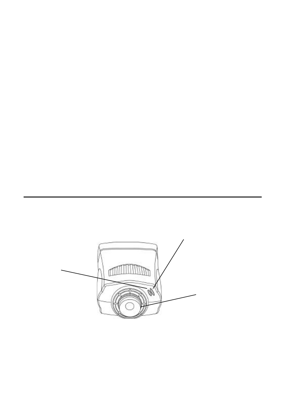
Physical Description
This section describes the externally visible features of DCS-1000.
Front Panel
Power LED
The Power LED is positioned on the right side of DCS-1000’s lens while
facing DCS-1000.Steady blue confirms DCS-1000 is powered on.
Note:
There are three settings for the Power LED to control the light illumination for
Power LED
LAN LED
Manual Focus Ring