Setup – BUG-O Systems Modular Drive System User Manual
Page 7
7
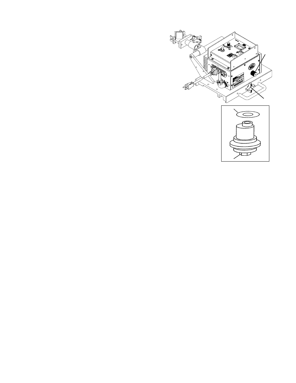
1) WHEEL ADJUSTMENT AND ALIGNMENT
Always check for proper carriage wheel adjustment before
using the machine. Turn the wheel engagement knob
(A)
on the side of the carriage until the wheels are fully moved
towards the center of the carriage (engaged). Then rotate
the master drive clutch knob
(B) fully counter clockwise to
disengage the drive pinion. Slide the carriage onto the end of
a track. The wheels should slide into the track V-grooves and
the carriage will move smoothly along the track if the wheels
are properly aligned.
The wheels along one side of the carriage have stainless steel shim wash-
ers
(C) underneath. These wheels are adjustable. Readjust these wheels (if
necessary) by rotating the hex bolt
(D) with a 1/2" wrench.
Grasp the sides of the carriage. The wheels are too loose if it is possible to
move the carriage from side to side or up and down. Use a finger to keep one
of the adjustable wheels from rotating as the carriage is manually pushed
along the track. The wheels are adjusted too tight if firm finger pressure is not
enough to prevent wheel rotation. Repeat the process for the other adjustable
wheel.
2) POSITIONING THE MACHINE ON THE TRACK
Position the rail using magnet plates or vacuum cups. Wipe the track grooves free of weld splatter and other
debris. This will prevent binding and premature rail and wheel wear. Lubricate the rack using a dry spray, if
desired, for extended track life.
Turn the wheel engagement knob
(A) on the side of the carriage fully counter clockwise to disengage the
wheels. Then rotate the Master Drive clutch knob
(B) fully counter clockwise to disengage the drive pinion.
The carriage can now be placed anywhere on the track. Turn the wheel engagement knob
(A) clockwise
to engage the wheels firmly in the V-grooves. Verify all four wheels are in the grooves. Manually move the
carriage along the track to verify the motion is smooth and the wheel alignment is correct. Rotate the Master
Drive clutch knob
(B) fully clockwise while gently rocking the machine forward and backward to fully engage
the drive pinion. The rocking motion is necessary to help insure proper gear mesh.
SETUP
C
D
B
A
3) REMOTE CONTACTOR WIRING
Connect the remote weld contactor to the welding source as shown below:
Pins A and B ................. connection for Output #1
Pins C and D ................ connection for Output #2
5) MACHINE OPERATION
Turn the main power ON at the power entry box. Set parameters on control module in use.
4) GUN AND TORCH SETUP
For welding, insert the welding gun into the all-position clamp on the rack. Adjust the clamp, the clamp block
and the rack to position the gun for welding. Connect the weld contactor connector to the rear of the main
drive unit. Route the welding cable and weld contactor wires through the cable anchor clamp.
For cutting, insert the cutting torch into the torchholder on the rack. Adjust the torchholder, the clamp block
and the rack to position the torch for cutting. Connect the hose assembly to the manifold and the cutting
torch. The manifold acts as a strain relief on the supply hoses as well as a quick shut-off valve for the gases.
Once the torch valves are adjusted, the manifold eliminates the need for continuous adjustments and keeps
the supply lines from dragging the torch out of position.