25 ... linear weaver / setup, Linear weaver setup, Dleft side c a b – BUG-O Systems Modular Drive System User Manual
Page 24
24
LINEAR WEAVER SETUP
1) WEAVER CONTROL MODULE AND LINEAR WEAVER INSTALLATION
Set the weave amplitude to maximum. Use the steering knob on the control module to move the crossarm to
both the extreme left and the extreme right. Perform measurements to determine if The crossarm is installed
too far left or too far right. Repeat the crossarm realigning procedure changing the 1 7/8" (48 mm) dimension
as required. Reinstall the two crossarm screws.
3) REALIGNING THE CROSSARM
(includes crossarm INSTALLATION and REMOVAL)
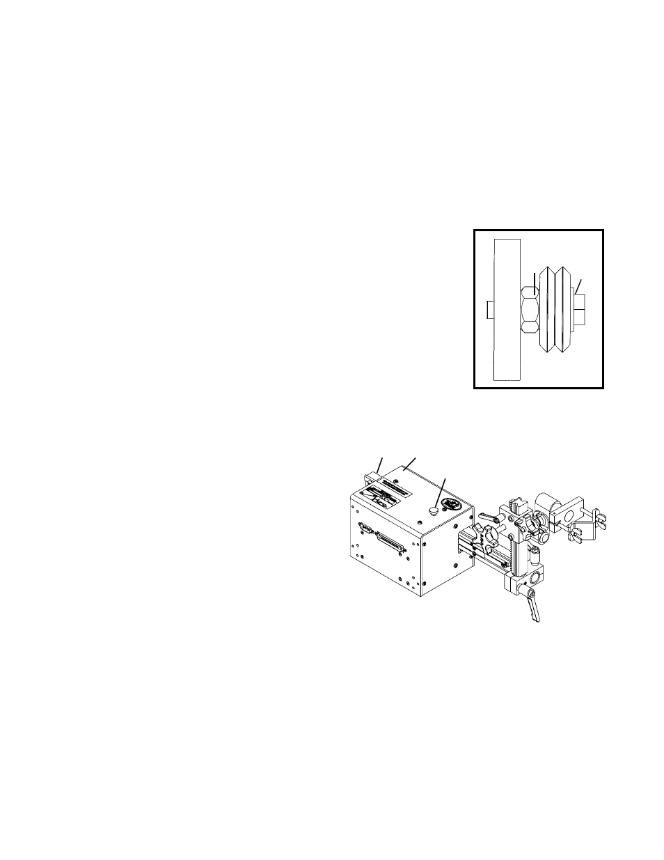
Check for proper alignment by using a finger to keep one of the wheels from
rotating while manually moving the crossarm. The wheels are adjusted too tight if
firm finger pressure is not enough to prevent wheel rotation. Once aligned, hold the
adjustment bushing
(B) still while tightening the hex bolt (A). Recheck alignment.
2) CROSSARM WHEEL ADJUSTMENT AND ALIGNMENT
The Weaver Control Module plugs into the top of the Master Drive Unit. Use a flat head screw driver to
firmly secure the four corners of the module.
Place the Linear Weaver on a flat surface, connector side up. Remove connector cover plate from MPD-1000.
Loosen, but do not remove, the bolts that hold the Master Drive Module to the carriage. Plug the Master Drive
Module into the Linear Weaver. The connectors should fit together easily and do not need forced. Attach
the Linear Weaver to the carriage using the two weaver mounting bolts.
DO NOT SUBSTITUTE LONGER
BOLTS. Retighten the bolts that hold the Master Drive Unit to the carriage.
Always check the crossarm wheel adjustment before using the machine. The
wheels are too loose and need adjustment if the crossarm can move up and
down. Normal gear backlash will permit crossarm side to side movement of
approximately 0.02" (0.5 mm).
If the wheels need adjustment, remove the left and right weaver end covers. The
two top wheels are adjustable. Loosen the hex bolt
(A) until the adjustable bushing
(B) can be rotated. Correct the wheel alignment by rotating adjustable bushing (B).
Rotate the clutch knob
(C) fully counterclockwise. This
disengages the drive pinion from the rack. Remove
the two socket head screws from the crossarm
(D). The
crossarm may be removed from or installed into the
Linear Weaver at this time.
Turn on the AC power. Rotate the four-turn steering
control knob and the weave speed knob on the Weaver
Control Module fully clockwise. Turn the start/stop
switch to START. Set the mode selector switch to NO
WEAVE. Align the crossarm
(D) so that 1 7/8" (48 mm)
of the crossarm protrudes from the left side of the Linear
Weaver. To insure proper gear mesh, gently rock the
crossarm back and forth about 1/16" (2 mm) while
engaging the pinion using the clutch knob
(C).
D
LEFT SIDE
C
A
B
CAUTION: IMPROPER GEAR
MESH MAY CAUSE PINION, RACK,
OR LINEAR WEAVER DAMAGE.