8 sensor principle, 9 needle valve principle, 10 constant-flow controller principle – Bronkhorst MASS-VIEW Series User Manual
Page 7
BRONKHORST HIGH‐TECH
9.17.051
MASS‐VIEW® series
Page 7
1.8 Sensor
principle
The MASS‐VIEW
®
operates on the principle of direct thermal mass flow
measurement. The thru‐flow design sensor consists of a heater resistor and a
temperature sensing resistor. Both resistors are made of temperature sensitive
resistive material that is covered with a stainless steel tube. The necessary heating
power to keep the temperature difference between the heater resistor and the
sensing resistor at a constant level depends on the mass flow. A different and
unique heater current is produced for each value of the flow. The measurement
principle described is called Constant Temperature Anemometry (CTA).
The transfer function between mass flow and output signal can be described by the
equation:
V
signal
= output signal
K
= constant factor
(includes λ – heat conductivity, C
p
– specific heat, μ – dynamic viscosity and ρ – density of the gas)
m
= mass flow
1.9 Needle
valve
principle
The needle valve has an orifice with a long, tapered conical seat. A needle‐
shaped plunger, on the end of a screw, exactly fits this seat. As the screw
is turned and the plunger retracted, flow between the seat and the
plunger increases. Since it takes many turns of the fine‐threaded screw to
retract the plunger, precise regulation of the flow rate is possible.
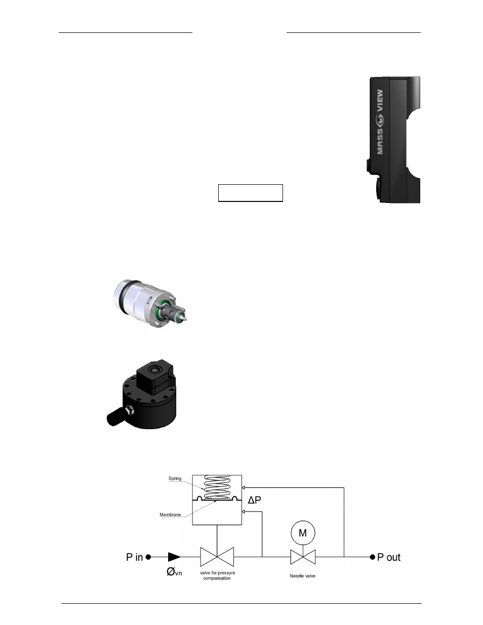
1.10 Constant-flow controller principle
Flow control with a needle valve at constant pressure results in a constant
flow rate. But when pressure conditions change, the flow will also change.
With a constant‐flow controller with varying upstream pressure the flow
will almost be constant.
By keeping the pressure drop across a needle valve constant the flow rate also is constant. Deviations of
the pressure drop are compensated by a membrane operated valve. This membrane is actuated by a
spring. The spring force closes the valve.
The equilibrium between closing (valve spring) and opening (membrane) keeps the flow constant.
Schematic flow diagram constant‐flow controller
m
signal
K
V