8 test pressure, 9 supply pressure – Bronkhorst MASS-VIEW Series User Manual
Page 12
BRONKHORST HIGH‐TECH
Page 12
MASS‐VIEW® series
9.17.051
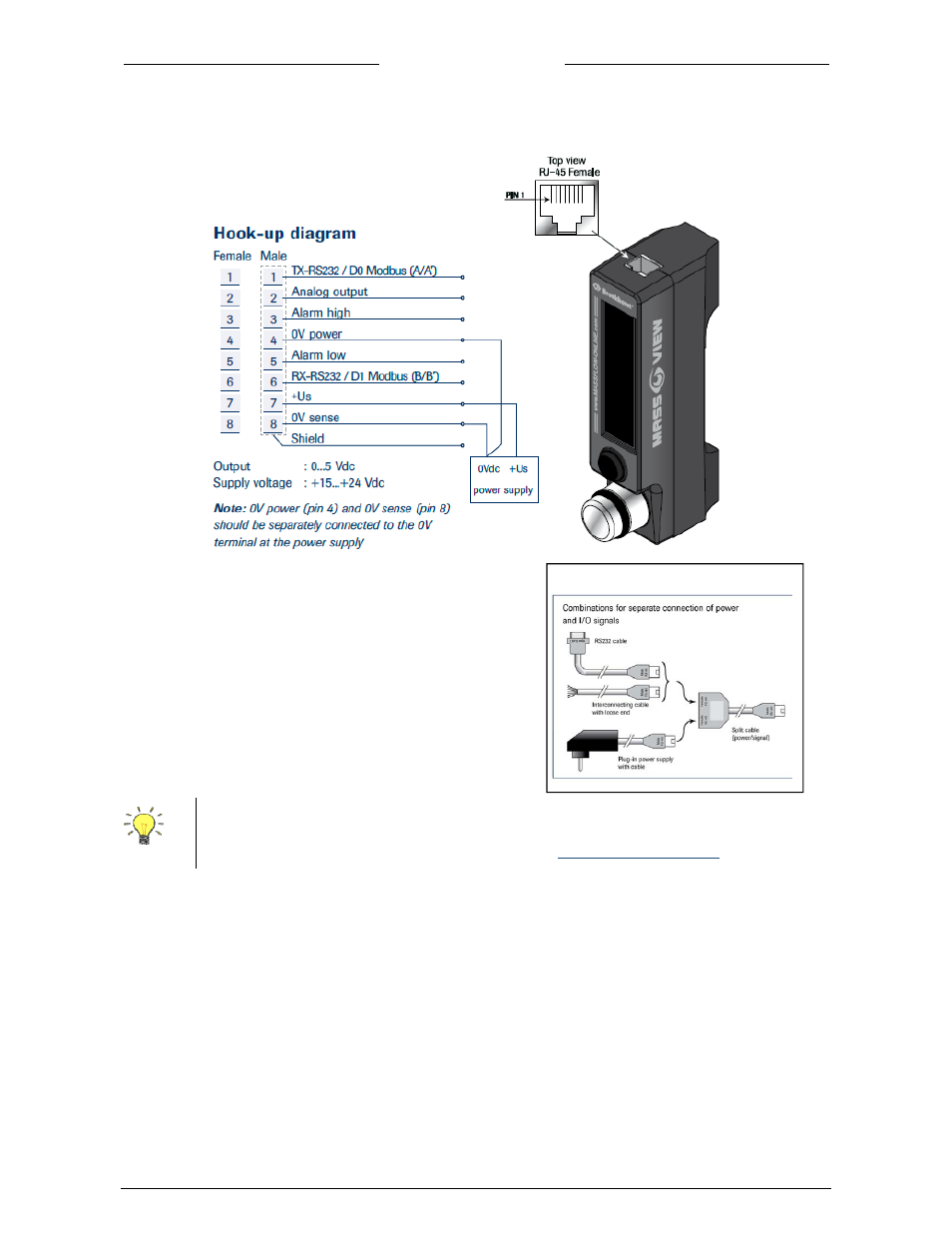
Please study carefully the hook‐up diagram which is shown here:
Depending on the mode of the digital output (which
can be changed through the user interface) the
function of pin 1 and pin 6 are:
Pin 1 = RS232 TXD or MODBUS D0
Pin 6 = RS232 RXD or MODBUS D1
Pin 2 = analog output
Pin 3 = alarm contact 1
Pin 5 = alarm contact 2
Pin 4 = 0V shared alarm contact for alarm 1/2
2.8 Test
pressure
Each instrument is pressure tested.
The tested pressure is stated on the instrument label.
The absolute maximum line pressure is 10 bar (g). Check test pressure before installing in the line. If the
label is not available or the test pressure is incorrect, the instrument should not be mounted in the
process line.
2.9 Supply
pressure
Do not apply pressure until electrical connections are made. When applying pressure to the system, take
care to avoid pressure shocks in the system and increase pressure gradually.
To use both the power supply and an analog or digital connection, you should use the optional
shielded RJ‐45 Y‐adapter.
All connector and cabling options can be purchased online:
www.massflow‐online.com
Available cabling options on massflow-online.com