Installation, Configuration – BECKHOFF C1300 User Manual
Page 42
C1300 VME to II/O Interface Unit
Beckhoff II/O-System
Page 42 of 44
Version : 2.01
Date : 18.12.95
5. Installation
5.1. Configuration
The central module C1300 needs only a single slot and can be installed in 3-HE and 6-HE
VMEbus crates. The connection to the II/O-system is established by two FO-plugs through the
front. The adjustment of the base address for the 4 kByte workspace occupied in the VME
address space is to be done by two DIP switches. The whole 16 MByte address space of the
VME system can be selected in the A24 mode as mapping area.
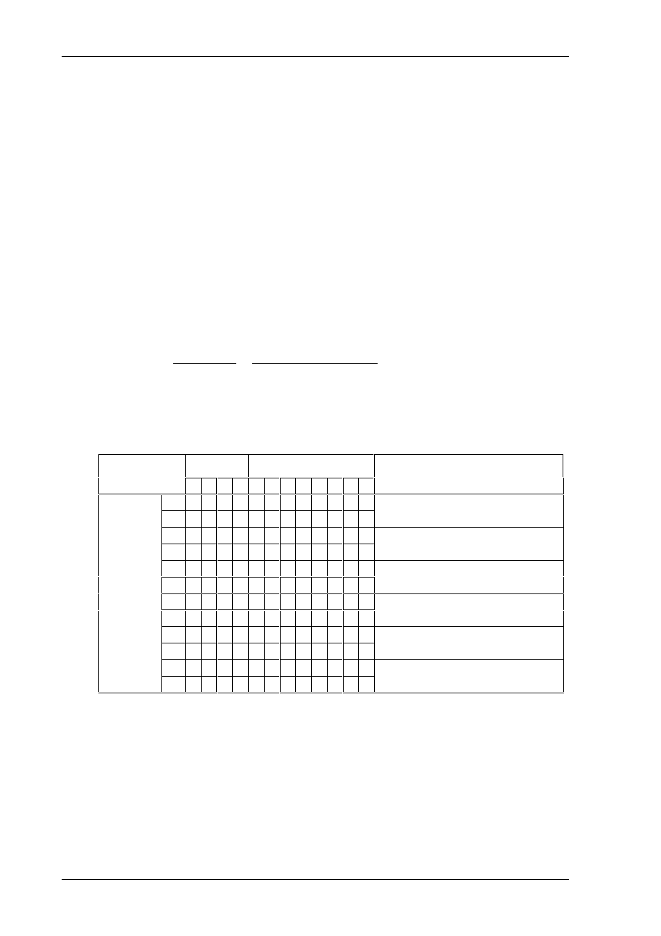
The switch positions represent the address lines A12-A23:
Switch:
SW100
SW101
1
2
3
4
1
2
3
4
5
6
7
8
Address Bit:
12 13 14 15
16 17 18 19 20 21 22 23
The switch position ”on” represents a logic 0, ”off” represents a logic 1.
Switch :
SW 100
SW 101
Address
1 2 3 4 1 2 3 4 5 6 7 8
Position
on
* * * * * * * *
00 0000h - 00 0fffh
off
on
* * * * * * *
10 0000h - 10 0fffh
off
*
on
* * * * * *
*
20 0000h - 20 0fffh
off
*
on
* * * * * *
30 0000h - 30 0fffh
off
* *
on * * *
* * * * * * *
80 8000h - 80 8fffh
off
*
*
on
ff f000h - ff ffffh
off * * * * * * * * * * * *