4 polarity test – BECKHOFF AL2000 Linear servomotor User Manual
Page 43
Electrical installation
T (ºC)
0
10
20
30
40
50
60
70
80
90
100
110
120
130
RKTY (Ω)
815
886
961
1040
1123
1209
1300
1394
1492
1594
1700
1810
1923
2041
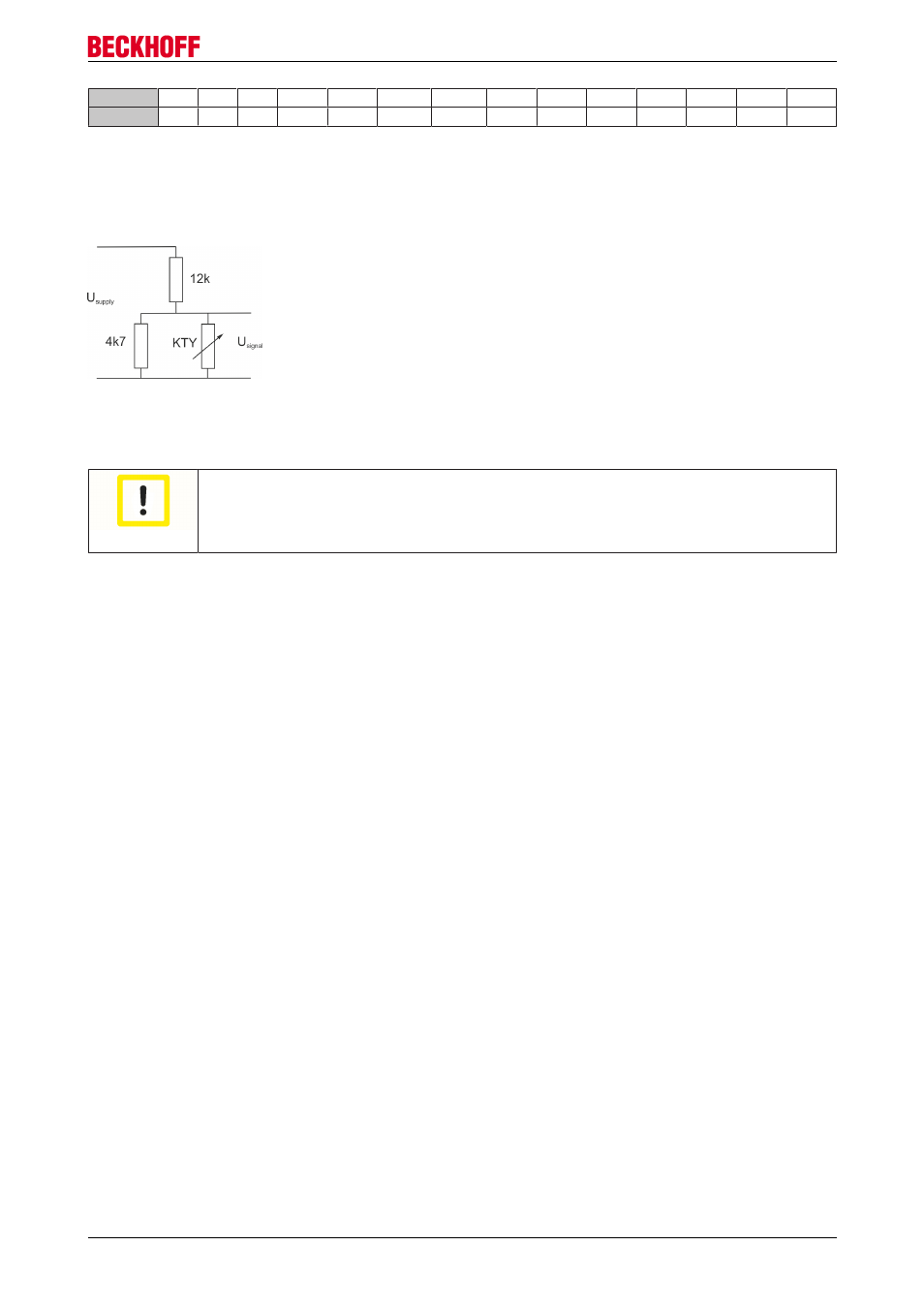
The sensor requires a continuous current of between 0 and 2 mA. The resistance does not respond linearly
to temperature. A linear current/temperature curve can be obtained with a resistance circuit as shown in the
diagram below. The basic tolerance is around ±5ºC (with shunt resistors).
8.4
Polarity test
Attention
Protection of the linear servomotor
Before the test, make sure that the linear motor system has suitable electrical and mechan
ical protection.
There is one way of checking the polarity. By means of moving the carriage it is possible to determine
whether the direction of movement of the motor corresponds to the count direction of the feedback. If this is
the case, the motor is connected correctly. Otherwise, two phases in the motor cable phases 1 and 3
must be swapped.
All linear servomotors from Beckhoff are wired and connected in exactly the same way, so that a single test
is sufficient in order to determine the polarity of a motor/graduated rule combination. If more than one axis is
being constructed in a similar way, the polarity will be identical.
Linear servomotor AL2xxx
43
Version 4.0