Figure 3-2. auto-synchronizer block diagram -2 – Basler Electric BE1-25A User Manual
Page 36
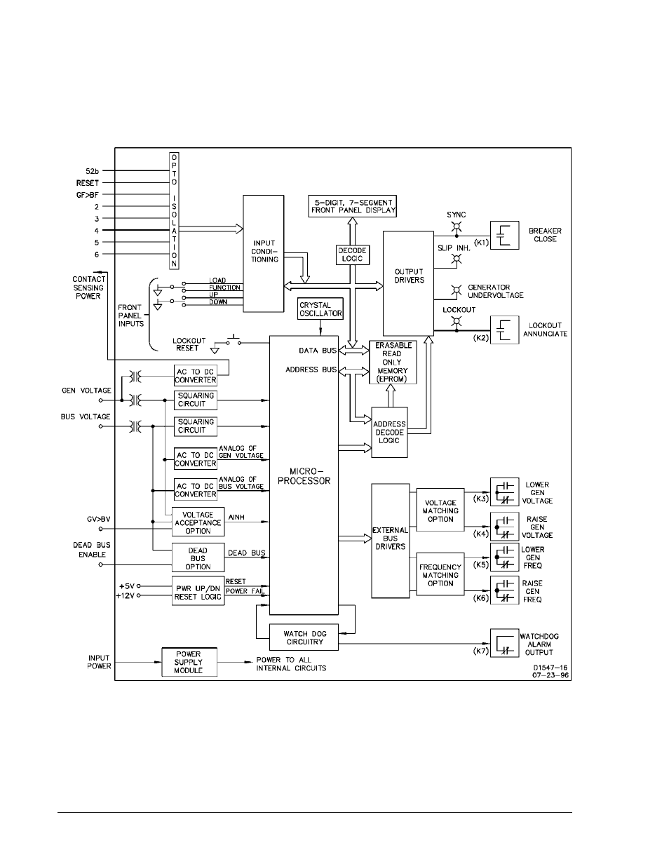
A functional block diagram of the Auto-Synchronizer is given in Figure 3-2, and is referred to in the circuit
descriptions that follow. A black box approach is taken, with the emphasis on the inputs and outputs to
the external world. Omitted from the diagram are the internal signals that communicate between the
various modules of the system. Note that the output relays shown in the lower right corner of the figure
are not present unless the controlling options are installed.
Later in this section, additional functional diagrams are provided that describe the options.
Figure 3-2. Auto-Synchronizer Block Diagram
3-2
BE1-25A Functional Description
9146600990 Rev S
See also other documents in the category Basler Electric Accessories for electrical:
- SMC-250 (6 pages)
- AVC63-2 (2 pages)
- AVC63-2.5 (2 pages)
- AVC63-4D (6 pages)
- AVC63-7 (4 pages)
- AVC63-7F (4 pages)
- AVC Sensing Module (2 pages)
- AVC125-10 (10 pages)
- AVC125-10 (14 pages)
- APR63-5 (6 pages)
- APR63-5X (4 pages)
- DECS-400 (250 pages)
- BE350 (4 pages)
- VR63-4/UL (2 pages)
- VR63-4A/UL (4 pages)
- VR63-4B (2 pages)
- VR63-4C/UL (2 pages)
- BE300PM (4 pages)
- DECS-100 (86 pages)
- DECS-250N Terminals and Connectors (370 pages)
- DECS-250 Mounting (4 pages)
- DECS-250N Mounting (4 pages)
- MVC232 (4 pages)
- MVC112 (8 pages)
- MVC236 (24 pages)
- BE2000E (82 pages)
- MVC300 (16 pages)
- CBS 212A (28 pages)
- MVC301 (16 pages)
- ICRM-15 (4 pages)
- DGC-2020 Troubleshooting (620 pages)
- DGC-2020ES (252 pages)
- DGC-2020HD (404 pages)
- DGC-2020ES Mounting (2 pages)
- DGC-2020HD Modbus Protocol (318 pages)
- RDP-110 (26 pages)
- IDP-800 (70 pages)
- ESD201 (4 pages)
- ESD202 (2 pages)
- IDP-1200 (90 pages)