Dead bus module d1, Dead bus module d1 -12, Figure 2-14. module d1 -12 – Basler Electric BE1-25A User Manual
Page 32
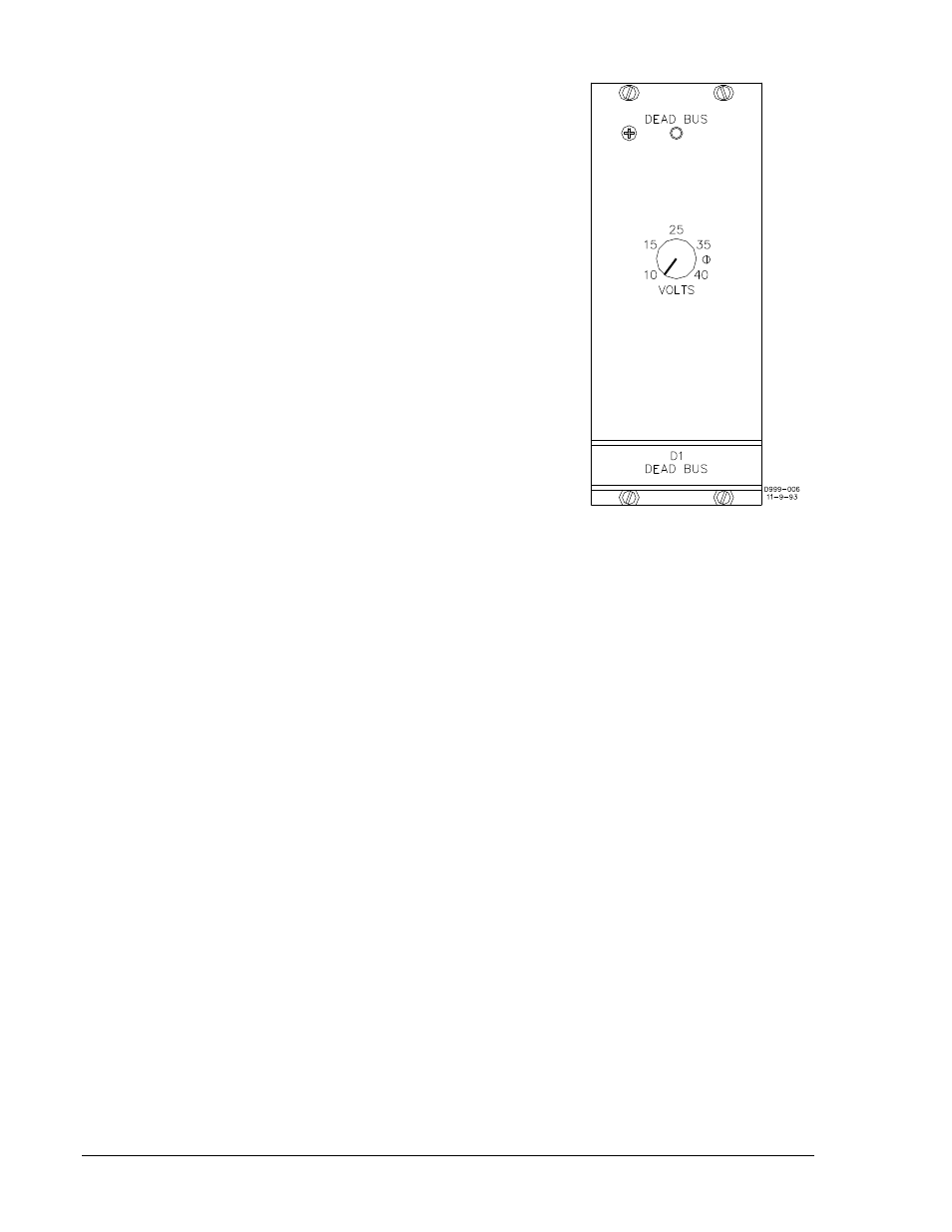
Dead Bus Module D1
When the external dead bus contact is closed, module D1 (Figure
2-14) determines when the bus is dead, and acts upon this
determination (if the breaker is detected open) by initiating a close
breaker signal. This signal is terminated as soon as the sync
acceptor recognizes the breaker as having closed, or when 100
milliseconds have passed (whichever occurs first).
The VOLTS control defines a dead bus condition by establishing a
voltage threshold between 10 and 40 Vac.
The DEAD BUS indicator is an LED that lights whenever the bus
voltage is below the control setting.
Figure 2-14. Module D1
2-12
BE1-25A Human-Machine Interface
9146600990 Rev S
See also other documents in the category Basler Electric Accessories for electrical:
- SMC-250 (6 pages)
- AVC63-2 (2 pages)
- AVC63-2.5 (2 pages)
- AVC63-4D (6 pages)
- AVC63-7 (4 pages)
- AVC63-7F (4 pages)
- AVC Sensing Module (2 pages)
- AVC125-10 (10 pages)
- AVC125-10 (14 pages)
- APR63-5 (6 pages)
- APR63-5X (4 pages)
- DECS-400 (250 pages)
- BE350 (4 pages)
- VR63-4/UL (2 pages)
- VR63-4A/UL (4 pages)
- VR63-4B (2 pages)
- VR63-4C/UL (2 pages)
- BE300PM (4 pages)
- DECS-100 (86 pages)
- DECS-250N Terminals and Connectors (370 pages)
- DECS-250 Mounting (4 pages)
- DECS-250N Mounting (4 pages)
- MVC232 (4 pages)
- MVC112 (8 pages)
- MVC236 (24 pages)
- BE2000E (82 pages)
- MVC300 (16 pages)
- CBS 212A (28 pages)
- MVC301 (16 pages)
- ICRM-15 (4 pages)
- DGC-2020 Troubleshooting (620 pages)
- DGC-2020ES (252 pages)
- DGC-2020HD (404 pages)
- DGC-2020ES Mounting (2 pages)
- DGC-2020HD Modbus Protocol (318 pages)
- RDP-110 (26 pages)
- IDP-800 (70 pages)
- ESD201 (4 pages)
- ESD202 (2 pages)
- IDP-1200 (90 pages)