Options, Operational test, Instructions – Basler Electric AVC63-12 User Manual
Page 9
Publication
9337200991
Revision
J
Instructions
Date
01/15
Page
9 of 10
OPTIONS
The AVC63-12 and AVC125-10 may be equipped with the following options to enhance operation.
Remote Voltage Adjust
Connect a 10 k
, 2 W potentiometer across terminals 6a and 7, remove the jumper from terminals 4 and 7, and
adjust the front panel VLT ADJ control fully clockwise to enable remote adjustment of the voltage setpoint.
Inrush Current Reduction Module
A Basler ICRM-15 is required when energizing the AVC63-12 or AVC125-10 from a source that is already at the
regulator input power rating. The ICRM-15 minimizes the amount of inrush current that could be seen when power
is applied.
Excitation Disable
This option disables excitation by removing power from the regulator. A switch removing voltage from terminals
26, 28 and/or 30 will remove regulator power.
Excitation Limiter
The Basler EL 200 provides an initial, fast-acting limit of the field current at a user-defined level. Once the field
current has changed to the selected level, the EL 200 provides a signal to the regulator to change the excitation
level.
Var/Power Factor Control
This option enables the AVC63-12 and AVC125-10 to regulate the var and power factor while the generator is
connected to an infinite or utility bus. The Basler SCP 250 supplies a dc signal into terminals 2 and 3 of the
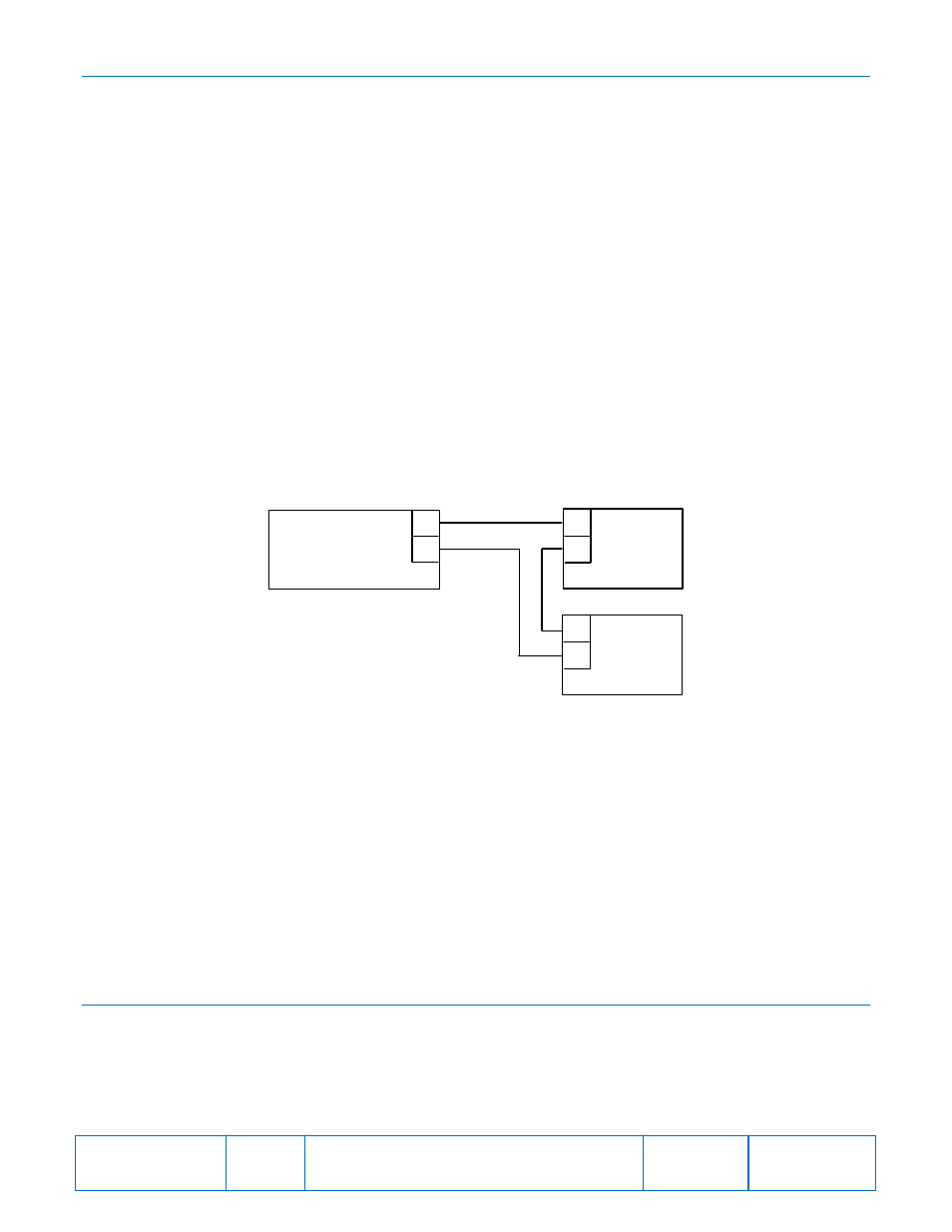
regulator to correct for vars or power factor. Figure 9 illustrates regulator and SCP 250 interconnection.
Figure 9. Interconnection with EL 200 and SCP 250
Current Boost System
With the CBS 212A option, if the generator output voltage decreases below the preset operating point due to a
short or large motor starting, the CBS 212A provides full current boost to the generator exciter until the voltage
returns to a level just above the operating point.
Manual Voltage Control
The Basler MVC-112 provides a method for manually controlling the generator output during generator startup
and commissioning or in the unlikely event of a regulator failure. Model MVC-112 is suitable for use with either the
AVC63-12 or AVC125-10 voltage regulator.
OPERATIONAL TEST
This test verifies AVC63-12 and AVC125-10 operation. Table 2 lists each regulator model and the corresponding
test voltage and frequency.
To test regulator operation, perform the following steps.
1.
Connect the regulator according to Figure 10 and apply the appropriate voltages.
2.
Adjust the VLT ADJ control fully counter-clockwise. Observe that the lamp is off.
L
C
2
3
Part of
AVC63‐12
or
AVC125‐10
Part of
EL 200
A
C
Part of
SCP 250
AVC units may be connected to either the
EL 200 or the SCP 250 using the
terminals as shown in place of this series
interconnection. See the unit instruction
manuals for more information.
When the AVC receives a positive voltage
(terminal 2 positive, terminal 3 negative)
at the Accessory input, the setpoint
decreases. A negative voltage (terminal 2
negative, terminal 3 positive) at the
Accessory input increases the setpoint.
P0009-25