Instructions – Basler Electric AVC63-12 User Manual
Page 2
Publication
9337200991
Revision
J
Instructions
Date
01/15
Page
2 of 10
Nominal Frequency
Option 1:
50 or 60 Hz
Option 2:
400 Hz
(See Table 2 for style/option information.)
Accessory Input
Voltage Range:
3 Vdc
Power Output
Maximum Continuous Output
AVC63-12:
12 Adc at 63 Vdc
AVC125-10:
10 Adc at 125 Vdc
10 Second Forcing Output
AVC63-12:
24 Adc at 125 Vdc
AVC125-10:
20 Adc at 250 Vdc
Minimum Field Resistance
AVC63-12: 5.25
AVC125-10: 12.5
Regulation Accuracy
0.5% of voltage setpoint, average response
Voltage Drift
0.5% variation for a 40C (104F) change
Response Time
<4 ms
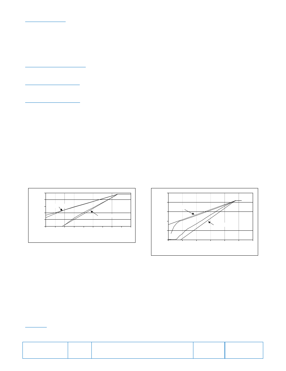
Frequency Compensation
One or two jumper-selectable V/Hz curves with knee frequency adjustable from 45 to 65 Hz (50/60 Hz units) or
300 to 430 Hz (400 Hz units). Figure 2 illustrates the 60 Hz sensing model and Figure 3 illustrates the 400 Hz
sensing model.
Figure 2. 60 Hz Sensing Model
Figure 3. 400 Hz Sensing Model
EMI Suppression
Internal filter. (See CE Conformity)
Voltage Buildup
Automatic voltage buildup occurs from residual generator voltage as low as 6 Vac (AVC63-12) or 12 Vac
(AVC125-10).
Overexcitation Shutdown
Overexcitation shutdown protection reduces the output voltage to zero in the times shown below for the listed
voltages. Other voltages and times are based on the inverse time characteristic curves of Figures 4 and 5
AVC63-12
125 Vdc,
10% in approximately 10 s
210 Vdc,
10% in approximately 1 s or less
0
50
100
150
200
250
20
25
30
35
40
45
50
55
60
65
Frequency In Hertz
T
e
rm
in
al
V
o
lt
ag
e
Ideal 1 PU/Hz
Ideal 2 PU/Hz
0
50
100
150
200
250
150
200
250
300
350
400
450
Frequency in Hertz
T
e
rm
in
a
l V
o
lt
a
g
e
in
V
o
lt
s
Ideal 2 PU/Hz
Ideal 1 PU/Hz