Instructions – Basler Electric AVC63-12 User Manual
Page 6
Publication
9337200991
Revision
J
Instructions
Date
01/15
Page
6 of 10
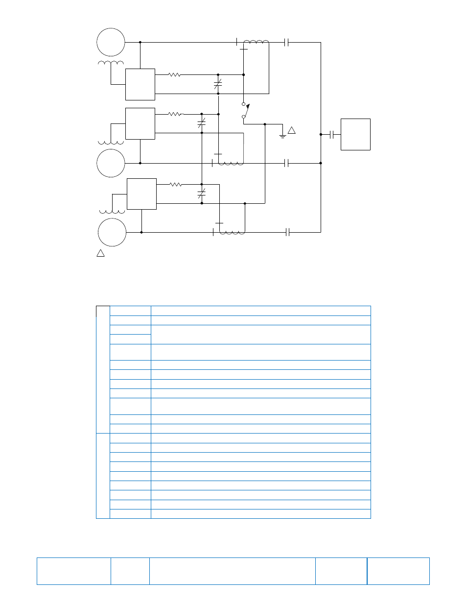
Figure 8. Connections for Cross-Current Compensation
Table 1. Terminal Descriptions
Term #
Description
Upper Termi
na
l Strip
CH GND
Chassis ground connection
2
Auxiliary input from SCP250 and/or EL 200 (See Fig. 7)
3
4
Internal voltage adjust: connect to 7. External voltage adjust: no
connection
5
1 A current transformer (CT)
5a
5 A CT
6
CT common connection
6a
Common connection for selectable features
7
Internal voltage adjust: connect to 4. External voltage adjust:
connect to 6a
8
Connect to 6a to select 1 V/Hz underfrequency slope
9
Connect to 6a to select 3-phase sensing
Lower Term. Strip
Term #
Description
20 C-phase sensing input
22 A-phase sensing input
24 B-phase sensing input
26
1- or 3-phase power input
28 3-phase power input
30
1- or 3-phase power input
F1
Field + connection
F2 Field
– connection
The secondary winding of a sensing transformer must be grounded as closely to the
transformer as practical. When interconnecting more than one transformer, ensure that
the secondary winding of only one transformer is grounded.
GEN 1
GEN 2
5 or 5A
6
AVC
0.1
0.1
CT
CT
LOAD
CCC
ENABLE
CONTACT
5 or 5A
GEN 3
0.1
CT
P0
009-
26.
vsd
0
3
-07-
12
5 or 5A
52b
1
52
1
52
2
52b
2
52b
3
52
3
AVC
AVC
6
6
1
The secondary winding of a sensing transformer must be grounded as closely to
the transformer as practical. When interconnecting more than one transformer,
ensure that the secondary winding of only one transformer is grounded.
1