Assembling adapter to test plug, Assembling adapter to test plug -4, Figure 7-2. sensing input connections – Basler Electric BE1-79M User Manual
Page 70: Table 7-1. test adapters
7-4
BE1-79M Difference Data
9170100990 Rev N
Table 7-1. Test Adapters
Power Supply Type
Test Adapter Part Number
24 V
None required
48 V
9170111100
125 V
9170111102
230 V
9170111104 ∗
CAUTION
∗
The surface of 230 V units may become hot.
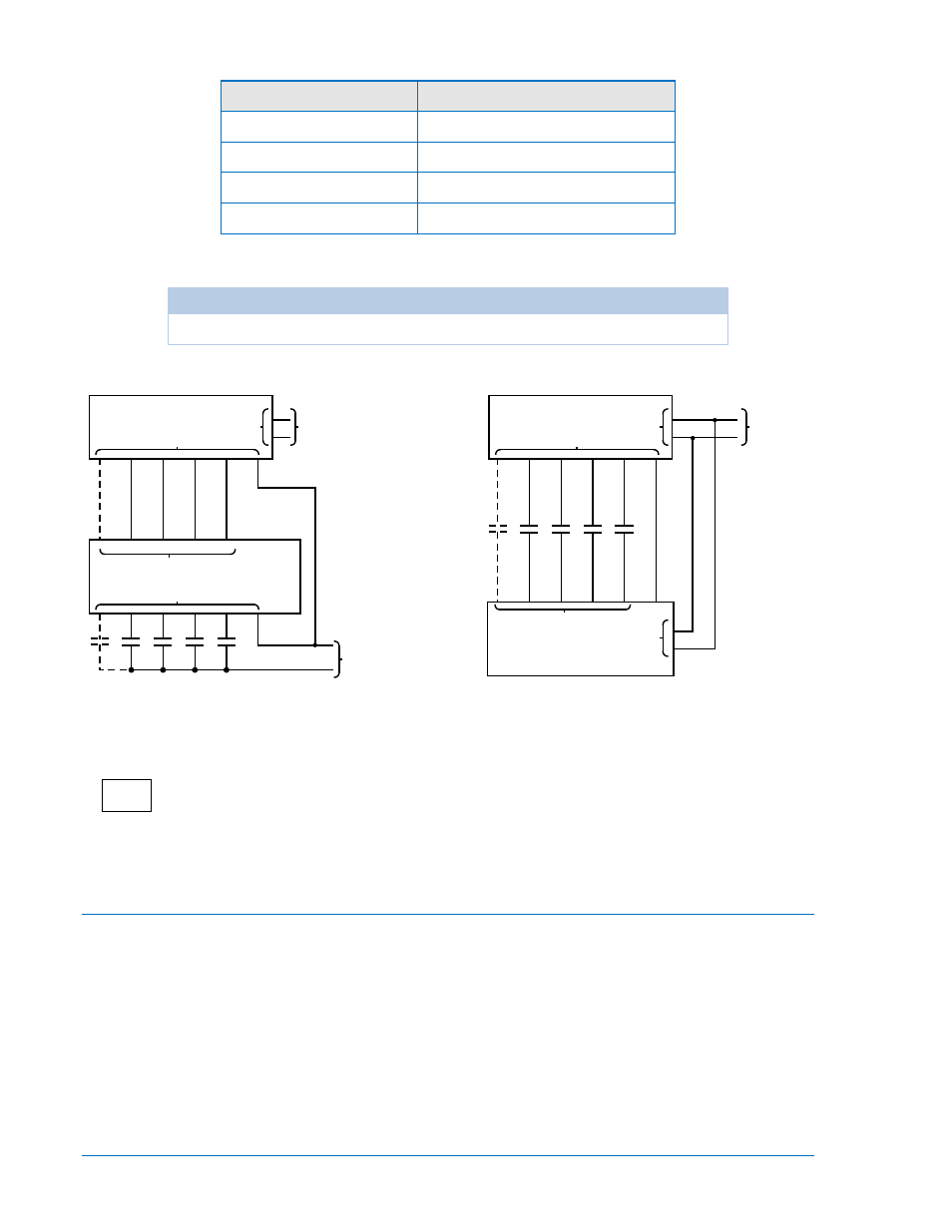
Figure 7-2. Sensing Input Connections
Assembling Adapter to Test Plug
STEP 1.
Remove top and bottom covers of test adapter by removing the 4 retaining screws.
STEP 2.
Remove ten black thumbnuts from test plug.
STEP 3.
The studs of the test plug may be entered into the ten matching holes of the adapter. Before
assembling the test plug to the adapter, it necessary to orient the two units to each other by
holding the black side of the test plug UP as it engages the adapter. (The adapter itself is
held topside UP - i.e. front panel letters are upright)
STEP 4.
Replace the ten black thumbnuts. Firmly hand-tighten each thumbnut.
STEP 5.
Replace top and bottom covers and fasten using 4 retaining screws removed in step 1.
P/N 9 1702 06 107 WITH PI
5
4
3
2
1
7
PI
RI
DTL
52b
IRB
-
+
SENSING
POWER
NON-ISOLATED SENSING
LEGEND:
RI RECLOSE INITIATE SENSING INPUT CONTACTS
DTL DRIVE-TO-LOCKOUT SENSING INPUT CONTACTS
52b CIRCUIT BREAKER SENSING INPUT CONTACTS
IRB INSTANTANEOUS RECLOSE BYPASS SENSING INPUT CONTACTS
PI PILOT INITIATE SENSING INPUT CONTACTS (OPTIONAL)
6-19-91
D806-009
BE1-79M
9
10
6
7
5
8
POWER
OPERATING
3
4
TB1
POWER MODULE
3
4
5
6
7
TB1
250 Vdc
230 Vac
TB2
TB1
SENSING
MODULE
P/N 9 1702 06 108 WITHOUT PI
250 Vdc
WITH TYPE Z
POWER SUPPLY
230 Vac
250 Vdc
TB1
POWER MODULE
TB1
4
3
OPERATING
POWER
8
5
7
6
10
9
P/N 9 1702 06 102 WITHOUT PI
MODULE
SENSING
TB2
1
2
3
4
5
P/N 9 1702 06 101 WITH PI
TB1
7
6
7
IRB
52b
DTL
RI
PI
POWER SUPPLY
WITH TYPE Z
ISOLATED SENSING