Reset, Lockout, Reset -7 – Basler Electric BE1-79M User Manual
Page 31: Lockout -7, Figure 3-4. power-up flow chart
9170100990 Rev N
BE1-79M Functional Description
3-7
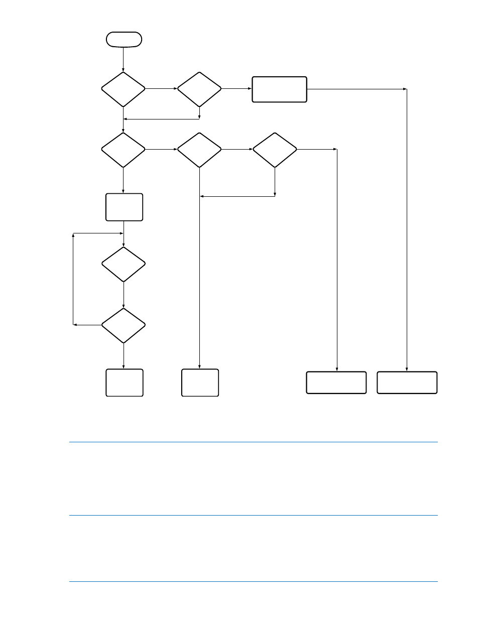
Figure 3-4. Power-up Flow Chart
Reset
A reclosing sequence may only be initiated when the relay is in RESET. RESET is indicated by a front
panel LED. For the relay to reach RESET, the controlled breaker must remain closed for the duration of
the reset time delay setting. If the breaker reopens prior to this time, the relay will proceed to the next
reclosing attempt. If the number of programmed reclosing attempts has been exhausted, the relay will
drive to LOCKOUT.
Lockout
LOCKOUT, a state inhibiting relay operation, is produced by any of the following conditions:
•
Number of breaker openings exceeds the number of programmed reclosure attempts
•
Closure of the drive-to-lockout input contacts
•
Reclose failure
•
Duration of a reclosing sequence exceeds the maximum cycle setting
POWER IS
APPLIED
IS
ENABLED
BREAKER
OPEN BEFORE
?
RESET
N
Y
MEMORY SAVE
?
TIMER
RESET
START
RESET
OUT
Y
?
TIMED
RESET
N
?
CIRCUIT
BREAKER
IS
OPEN
N
Y
N
Y
Y
N
Y
N
ENABLED
IS
TO RECLOSE
POWER UP
?
?
LOST DURING
REC. SEQ.
POWER
?
POWER
LOST WHILE IN
RESET
N
Y
RESTORE OUTPUT
STATES
(OPEN RELAY FAIL)
< 0.1 SEC.
LOCKOUT
PROGRAMMED
RECLOSE WITH FIRST
RECLOSE
SEQUENCE
RECLOSING
CONTINUE
D0757-12