Data retrieval, Data retention, Data retrieval -12 – Basler Electric BE1-79M User Manual
Page 36: Data retention -12, Table 3-4. rem data retrieval modes
3-12
BE1-79M Functional Description
9170100990 Rev N
Data Retrieval
In order to retrieve data from REM, the relay must first be taken out of service and placed in the test
mode. Do this by setting the logic board NORMAL/TEST switch (see Figure 2-1) to the TEST position.
Then set the front panel RESET thumbwheel switch to 00. The relay is now ready for data retrieval.
Before proceeding, notice that the following controls and indicators are re-defined whenever the REM
function is in use.
RECLOSE TIME thumbwheel #3 (least significant digit only)
- Selects the type of event for which data
is to be retrieved. Refer to
for event and switch positions.
STATUS LEDs (INST., #1 and #2)
- Verify that the digit selected on RECLOSE TIME thumbwheel #3
is correct. The STATUS LEDs will be ON as shown in
RECLOSE TIME thumbwheel #1 (3 digits)
- Indicates the number of accumulated events when ma-
nually rotated so that RESET LED and STATUS #3 LED are both ON.
STATUS LED #3
- Means "<" (less than).
RESET LED
To retrieve REM data, complete the following procedure.
- Means ">" (greater than).
•
Remove relay from service and position NORMAL/TEST switch to TEST.
•
Position RESET thumbwheel switch to 00.
•
Select the type of event (MODE) desired by setting RECLOSE TIME thumbwheel #3 as indicated
in Table 3-4.
•
Verify that the desired mode is selected by observing the INST., #1, and #2 STATUS LEDs.
•
Observe the STATUS LED #3 and RESET LED. These indicators identify whether the number
selected on RECLOSE TIME #1 thumbwheel is less (STATUS LED #3 ON) or greater (RESET
LED ON) than the number stored in memory.
•
Position RECLOSE TIME #1 thumbwheel until both STATUS LED and RESET LED are ON.
When both indicators are ON, the selected number on RECLOSE TIME #l thumbwheel setting is
equal to the stored number.
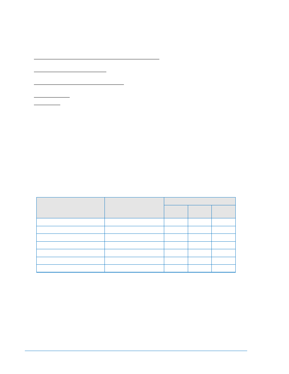
Table 3-4. REM Data Retrieval Modes
Type of Event
RECLOSE TIME
#3 Thumbwheel
(Least Significant Digit)
STATUS LED
INST
#1
#2
Instantaneous
0
0
0
0
1st time delayed
1
0
0
1
2nd time delayed
2
0
1
0
3rd time delayed
3
0
1
1
Pilot reclosure
4
1
0
0
Unsuccessful reclosures
5
1
0
1
None
Any other
1
1
1
NOTE: A "1" in the STATUS Indication column indicates LED is ON.
Data Retention
To retain data stored in memory and resume the event count,
•
Position the NORMAL/TEST switch on the logic board to NORMAL.
•
Return front panel controls to their regular settings.
•
Place the relay back in service.