Avalon Firestyles Surround Panels User Manual
Surround panels (dvs/dvl ef ii), Compatibility, Packing list
Surround Panels (DVS/DVL EF II)
Page 1 of 2
17601428 - 2/25/14
© Travis Industries, Inc.
Compatibility
DVS Insert EF II
DVL Insert EF II
Packing List
Top, Right, and Left Side Panels
Panel Trim (with Hardware)
(4) 10-24 Type F Thread-Cutting Screws
(7) Spring Clips
Part Numbers
DVS – 4” by 6”
96100300
DVS – 8” by 10”
96100301
DVS – 10” by 13”
96100302
DVL – 4” by 6”
96100320
DVL – 8” by 10””
96100321
DVL – 10” by 13”
96100322
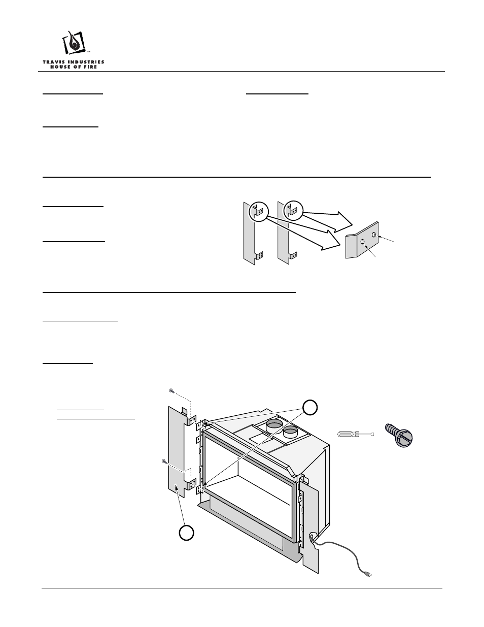
Arched Faces with Screens (2014 or later) Require Use of the Extended Position Holes
This surround panel has 2 sets of holes. Hole position is
determined by the face being used (see below)
Standard Position – used for all faces except for the new
2014 arched faces with screens. All other faces use the
standard position hole. If you are uncertain, use the standar
position.
Extended Position – used only for new arched faces with
screens (2014 or later). The extended position allows room
the screen and eliminates the ½” gap to the panel. The
extended position hole positions the insert ½” farther into the
fireplace cavity.
Rheostat and On/Off Switch Placement on 33 DVI/31 DVI
Install the rheostat and On/Off switch on the right surround side surround panel (see the Owner’s Manual for details).
Inside Fit Panels
The panels may be cut down in size and placed within the fireplace opening. When installed in this configuration, install the
rheostat and on/off switch in the control panel under the firebox (see the owner’s manual for details). For standard installations, we
recommend you attach the rheostat and on/off switch to the upper right surround panel trim (after the trim is installed).
Installation
Before installation the insert should be in place with the gas line and vent attached. Pull the insert out slightly to assist in the
installation. Attach the side panels then the top panel and trim (see the directions below and on the following page).
DVS / 31 DVI
Side Panel Installation
Extended
Position
Standard
Position
DVS Side
Panel
DVL Side
Panel
Line up each side surround
panel and insert two screws from
the inside to secure in place.
5/16" Nutdriver
Pre-thread the holes on the brackets
screws included in the surround panel kit.
b
a
Run the power cord to
the side of the insert.