2 fabric front blade port mapping, 3 bcm84740 configuration flash, 4 transmitter control – Artesyn RTM ATCA-F140 Installation and Use (July 2014) User Manual
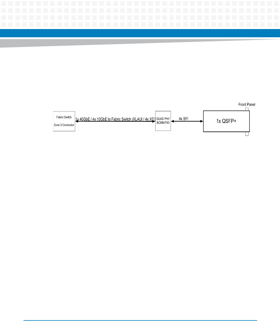
Page 45: Figure 4-5, Fabric 40gb interconnect
Functional Description
RTM-ATCA-F140 Installation and Use (6806800M97F)
45
0.1μF AC-coupling capacitors on the XLAUI inputs from the front blade. Similarly capacitors are
expected to be provided on the front blade for signals from the RTM. The QSFP+ specification
requires AC-coupling capacitors in the module so they are not needed on the board SFI
interface.
4.6.2
Fabric Front Blade Port Mapping
Each fabric switch port on the front blade consists of four SERDES pairs. The four fabric channel
XLAUI pairs connect to front blade port FIX_P14. This is a dedicated port on the ATCA-F140
front blade fabric switch.
4.6.3
BCM84740 Configuration Flash
The BCM84740 requires an external SPI Flash to store microcode for the internal
microcontroller. A single SPI Flash is connected to the FPGA and the SPI bus from the
BCM84740 is similarly connected to the FPGA. Register settings in the FPGA allow the
BCM84740 to connect to the SPI Flash as well as provide a programming port.
4.6.4
Transmitter Control
QSFP+ does not define a hardware signal for transmitter control. Software controls the
transmitter via byte 86 in the QSFP+ memory map. Refer to the QSFP+ Specification for further
detail.
The TXONOFF signal on the BCM84740 is connected to the RTM FPGA which allows it to be
driven under software control. When asserted, this signal will cause the PHY to drive LPMODE
to the QSFP+ site. This places the PHY and QSFP+ module into low-power mode but may not
actually disable the QSFP+ transmitters, according to the QSFP+ specification. Transmitter
control should be performed through the software method detailed above.
Figure 4-5
Fabric 40Gb Interconnect