4 i2c address map, 3 1 gbps sfp ports, 1 connectivity – Artesyn RTM ATCA-F140 Installation and Use (July 2014) User Manual
Page 36: Table 4-3, I2c bus address map, Figure 4-2, 1gb base channel interconnect, Functional description
Functional Description
RTM-ATCA-F140 Installation and Use (6806800M97F)
36
The I/O expander resides at I2C address 0x40.
4.2.4
I2C Address Map
summarizes the I2C address assignments.
4.3
1 Gbps SFP Ports
The RTM-ATCA-F140 provides four 1 Gbps SFP module sites which are connected to the front-
blade base switch.
4.3.1
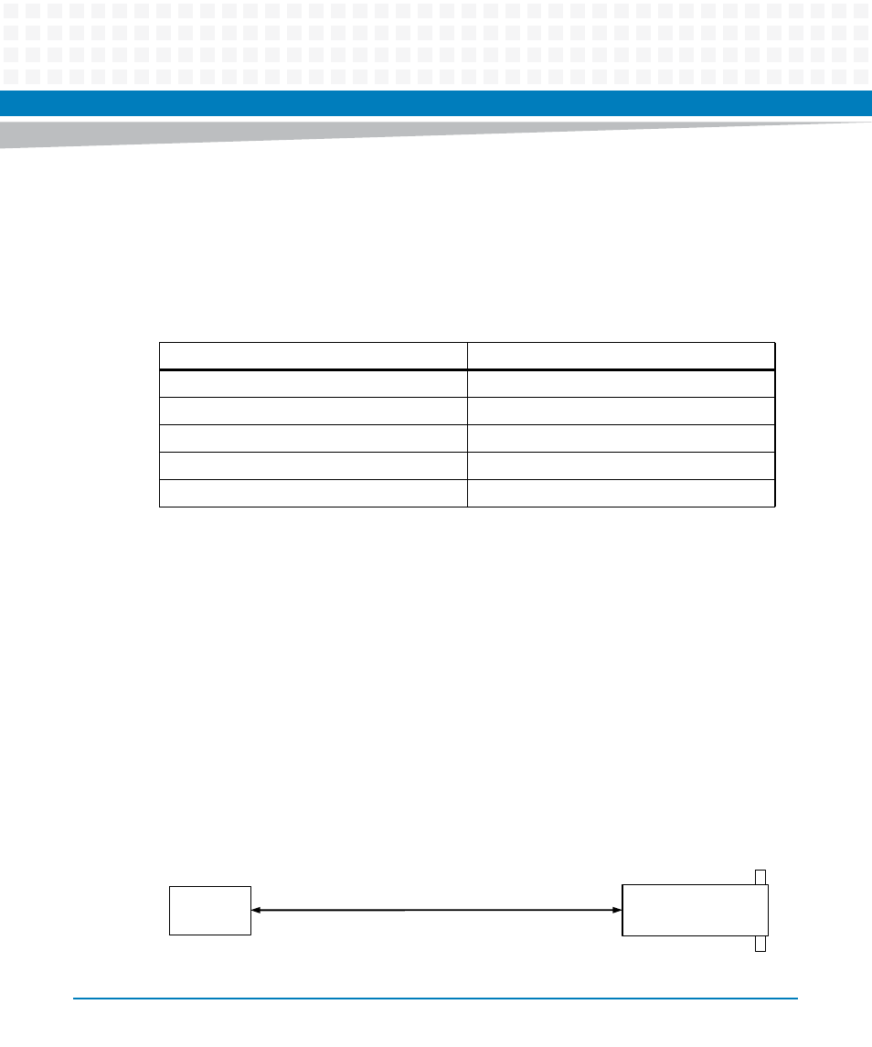
Connectivity
Four 1000Base-BX serdes connections from the front-blade are routed directly from the zone
3 connectors to four SFP sites as shown in
. These are all dedicated ports on the front
blade base switch. The RTM-ATCA-F140 does not include AC-coupling capacitors on the inputs
from the front blade since they are provided by the SFP module.
Table 4-3 I2C Bus Address Map
Address
Device
0x40
I/O Expander (LED control)
0x90
Temperature sensor (top)
0x92
Temperature sensor (middle)
0x94
Temperature sensor (bottom)
0xA0
Serial EEPROM
Figure 4-2
1GB Base Channel Interconnect
4x SFP
4x 1GbE to Base Switch (SGMII)
Front Panel
Base Switch (BIX)
Zone 3 Connector