2 front-blade port mapping, 3 sfp connection, 2 front-blade port mapping 4.3.3 sfp connection – Artesyn RTM ATCA-F140 Installation and Use (July 2014) User Manual
Page 37: Table 4-4, Front-blade port mapping, Table 4-5, Sfp connector pin assignment, Functional description
Functional Description
RTM-ATCA-F140 Installation and Use (6806800M97F)
37
4.3.2
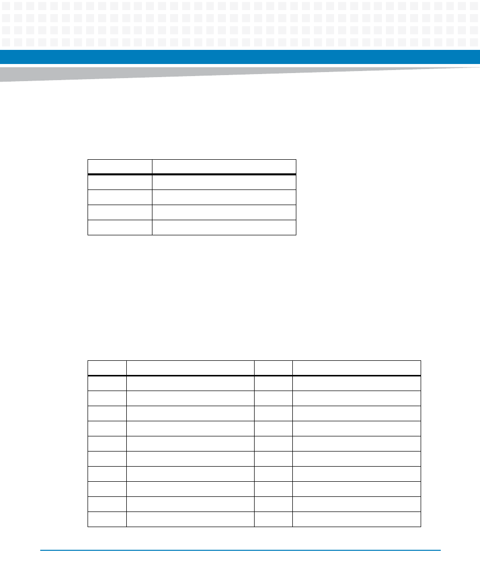
Front-Blade Port Mapping
The four SFP sites are connected to the front-blade base switch according to the table below.
4.3.3
SFP Connection
The SFP sites allow the fitting of a wide range of third-party SFP modules to support 1000Base-
T, long and short range optical connection. Refer to the ATCA-F140 Installation and Use Manual
for a list of SFP devices tested with this product.
The following table shows the SFP connector pin assignments.
Table 4-4 Front-Blade Port Mapping
RTM Port
Front Blade Base Switch Port
ETH1
ge20
ETH2
ge21
ETH3
ge22
ETH4
ge23
Table 4-5 SFP Connector Pin Assignment
Pin
Signal
Pin
Signal
1
GND
11
GND
2
TX_FAULT
12
RX-
3
TX_DISABLE
13
RX+
4
I2C_SDA
14
GND
5
I2C_SCL
15
VCCr (+3.3V)
6
MOD_ABS
16
VCCt (+3.3V)
7
RATE_SEL
17
GND
8
LOS
18
TX+
9
GND
19
TX-
10
GND
20
GND