1 fabric connectivity, 2 fabric front blade port mapping, 3 bcm84754 configuration flash – Artesyn RTM ATCA-F140 Installation and Use (July 2014) User Manual
Page 42: 4 transmitter control, Figure 4-4, Fabric 10gb interconnect
Functional Description
RTM-ATCA-F140 Installation and Use (6806800M97F)
42
4.5.1
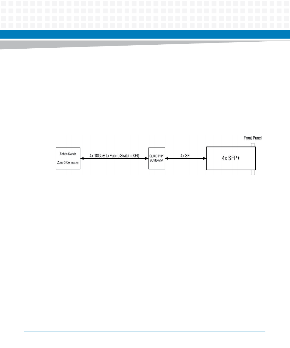
Fabric Connectivity
Four 10GbE ports (configured for XFI mode) from the front blade fabric switch connect to a
BCM84754 quad XFI-to-SFI PHY which then connects to four individual SFP+ connectors using
an SFI interface as shown in
. The RTM-ATCA-F140 includes 0.1μF AC-coupling
capacitors on the XFI inputs from the front blade. Similarly, capacitors are expected to be
provided on the front blade for signals from the RTM. The SFP+ specification requires AC-
coupling capacitors in the module so they are not needed on the board SFI interface.
4.5.2
Fabric Front Blade Port Mapping
Each fabric switch port on the front blade consists of four SERDES pairs. The four fabric channel
XFI ports connect to front blade port FIX_P15. This is a dedicated port on the ATCA-F140 front
blade fabric switch.
4.5.3
BCM84754 Configuration Flash
The BCM84754 requires an external SPI Flash to store microcode for the internal
microcontroller. A single SPI Flash is connected to the FPGA and the SPI bus from the
BCM84754 is similarly connected to the FPGA. Register settings in the FPGA allow the
BCM84754 to connect to the SPI Flash as well as provide a programming port.
4.5.4
Transmitter Control
The TXONOFF signals on the BCM84754 are individually connected to the RTM FPGA which
allows them to be driven under software control. This enables software to enable and disable
the SFP+ optical outputs.
Figure 4-4
Fabric 10Gb Interconnect