Table 5-5, Transition module leds, Table 5-6 – Artesyn MVME4100 Single Board Computer Installation and Use (June 2014) User Manual
Page 87: Mvme721 host i/o connector (j10) pin assignments, Transition module
Transition Module
MVME4100 Single Board Computer Installation and Use (6806800H18G)
87
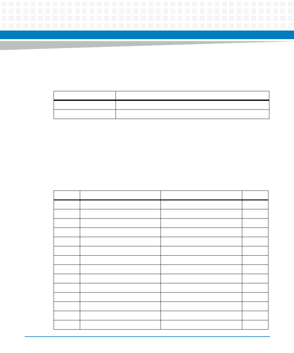
There are two sets of ACT and SPEED LEDs, one set for each Ethernet connector. They are
described in the next table.
5.5.1
MVME7216E PMC I/O Module (PIM) Connectors (J10, J14)
PMC Host I/O connector J10 routes only power and ground from VME P2. There are no Host I/O
signals on this connector. The MVME4100 routes PMC I/O from J14 of PMC Slot 1 to VME P2
rows A and C. The MVME7216E routes these signals (pin-for-pin) from VME P2 to PMC I/O
Module connector J14. See
for the pin assignments.
Table 5-5 Transition Module LEDs
LED
Function
ACT
Activity for Ethernet or Gigabit E Ethernet connector
SPEED
10/100/1000Mb/s of Ethernet connectors
Table 5-6 MVME721 Host I/O Connector (J10) Pin Assignments
Pin
Signal
Signal
Pin
1
No Connect
No Connect
2
3
No Connect
No Connect
4
5
+5V
No Connect
6
7
No Connect
No Connect
8
9
No Connect
+3.3V
10
11
No Connect
No Connect
12
13
GND
No Connect
14
15
No Connect
No Connect
16
17
No Connect
GND
18
19
No Connect
No Connect
20
21
+5V
No Connect
22
23
No Connect
No Connect
24
25
No Connect
+3.3V
26
27
No Connect
No Connect
28