Introduction – Artesyn MVME4100 Single Board Computer Installation and Use (June 2014) User Manual
Page 20
Introduction
MVME4100 Single Board Computer Installation and Use (6806800H18G)
20
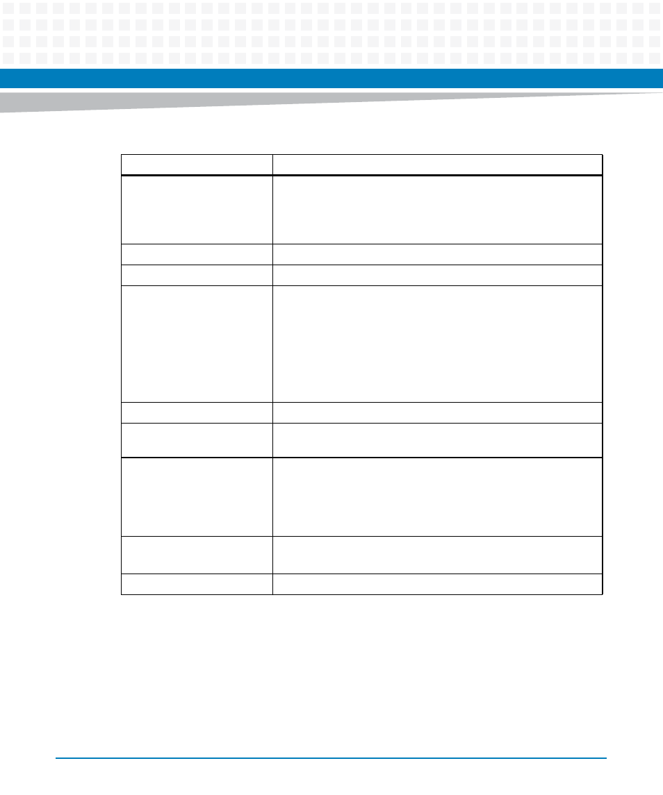
Flash
128 MB soldered NOR flash with two alternate 1 MB boot sectors
selectable via hardware switch
H/W switch or S/W bit write protection for entire logical bank
4 GB NAND flash
NVRAM
One 512 KB MRAM
PCI_E
8X Port to XMC Expansion
I/O
One front panel mini DB-9 connector for front I/O: one serial channel
Two front panel RJ-45 connectors with integrated LEDs for front I/O:
two 10/100/1000 Ethernet channels
One front panel USB Type A upright receptacle for front I/O: one USB
2.0 channel
PMC site 1 front I/O and rear P2 I/O
PMC site 2 front I/O
USB
One four-channel USB 2.0 controller: one channel for front panel I/O
Ethernet
Four 10/100/1000 MPC8548E Ethernet channels: two front panel
Ethernet connectors and two channels for rear P2 I/O
Serial Interface
One 16550-compatible, 9.6 to 115.2 Kbaud, MPC8548E,
asynchronous serial channel: one channel for front panel I/O
One quad UART (QUART) controller to provide four 16550-
compatible, 9.6 to 115.2 Kbaud, asynchronous serial channels: four
channels for rear P2 I/O
Timers
Four 32-bit MPC8548E timers
Four 32-bit timers in a PLD
Watchdog Timer
One watchdog timer in PLD
Table 1-1 Features List (continued)
Function
Features