Argox OS-2130D User Manual
Page 35
56
OS-2130D & OS-2130DE User’s Manual
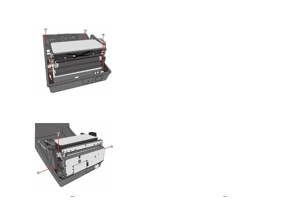
4. Remove the whole print head assembly by releasing 4 screws at its
feet.
Figure 6.3
5. Add a cutter baby board to J5 on the main board.
6. Secure three attached screws for the cutter.
Figure 6.4
57
OS-2130D & OS-2130DE User’s Manual
7. Plug the cutter's connector into the PCB's header connector (J3).
8. Reinstate the print head assembly by securing back the 4 screws.
9. Click back the middle cover.
10. Secure two screws back at base housing.
11. Install the top cover.