F_panel – Aplex Technology OPC-5127 User Manual
Page 26
OPC-5XX7 User Manual
26
IOW#
23
24
Ground
IOR#
25
26
Ground
IOCHRDY
27
28
Ground
DACK#
29
30
Ground
IRQ14
31
32
NC
Address 1
33
34
IDE_PDIAG
Address 0
35
36
Address 2
Chip select 0 37
38
Chip select 1
Activity
39
40
Ground
+5V
41
42
+5V
Ground
43
44
NC
Note:
If two IDE devices are connected, CF card connection cannot be realized.
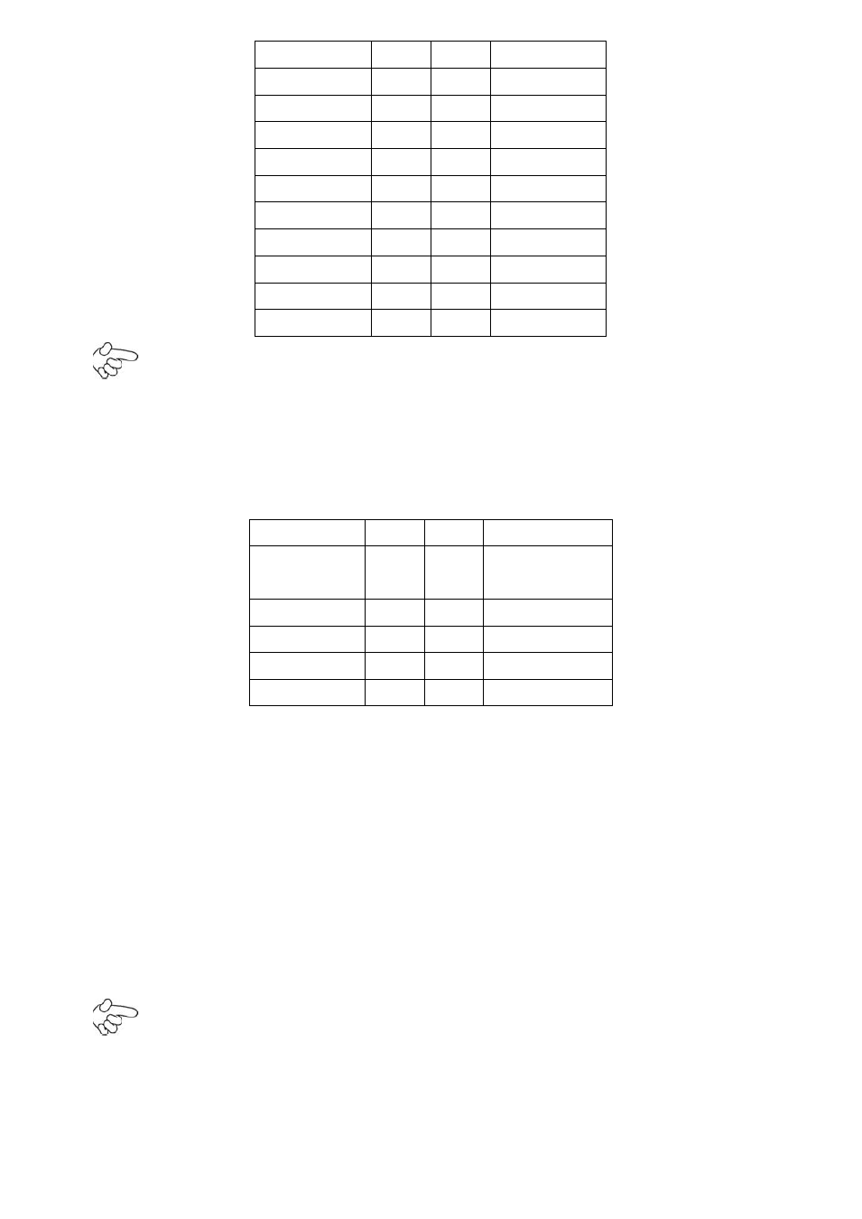
12. F_PANEL
(2.0MM 2X5)
Front panel connector
Signal Name Pin#
Pin#
Signal Name
HD LED+
1
2
POWER
LED+
HD LED-
3
4
POWER LED-
Ground
5
6
PWRBTN
RESET
7
8
Ground
BUZZER+
9
10
BUZZER-
PIN1&3: They are used to connect hard disk activity LED. The LED blinks when the hard disk is
reading or writing data.
PIN2&4: They are used to connect power LED. When the system is powered on or under S0/S1
state, the LED is normally on; when the system is under S4/S5 state, the LED is off.
PIN5&6: They are used to connect power switch button. The two pins are disconnected under
normal condition. You may short them temporarily to realize system startup & shutdown or
awaken the system from sleep state.
PIN7&8: They are used to connect reset button. The two pins are disconnected under normal
condition. You may short them temporarily to realize system reset.
PIN9&10: They are used to connect an external buzzer.
Note:
When connecting LEDs and buzzer, pay special attention to the signal polarity.
Make sure that the connector pins have a one-to-one correspondence with chassis wiring, or it
may cause boot up failure.