Jcom – Aplex Technology OPC-5127 User Manual
Page 25
OPC-5XX7 User Manual
25
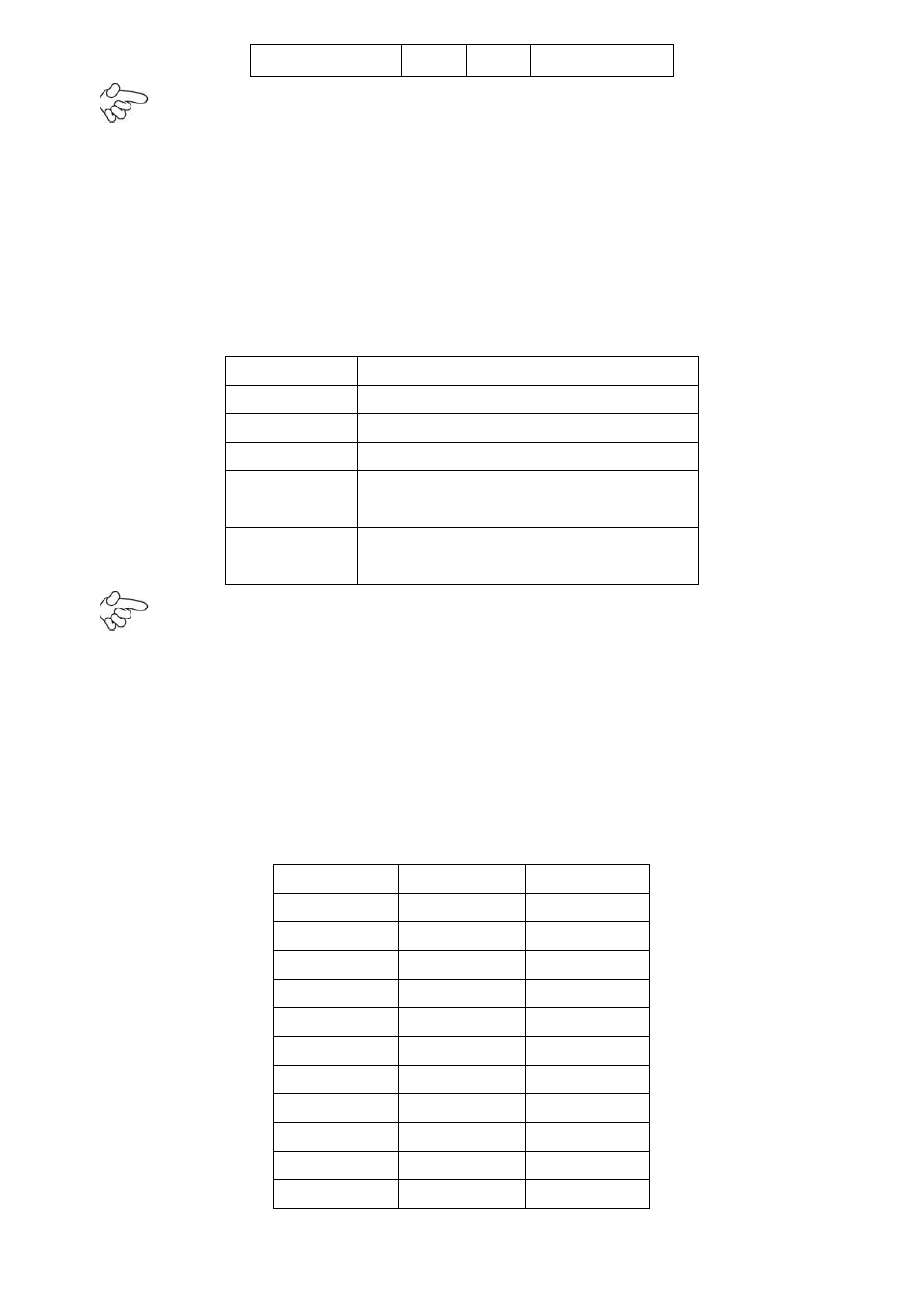
NC
9
10
Ground
Note:
Before connection, make sure that pin out of the USB adapter is in accordance with that of the
said tables. Any inconformity may cause system down and even hardware damages.
10. JCOM
(2.0MM 2X6)
COM1/2 setup jumper: pin 1~6 are used to select signal out of pin
9 of COM1 port; pin 7~12 are used to select output type for COM2 port (RS232 or RS422/485
Full-Duplex).
JCOM
Function
CLOSE 1-2
COM1 Pin9=RI (default)
CLOSE 3-4
COM1 Pin9=+5V
CLOSE 5-6
COM1 Pin9=+12V
CLOSE 7-9
CLOSE 8-10
COM2 FOR RS232 FROM COM2
(default)
CLOSE 9-11
CLOSE 10-12
COM2 FOR RS485/RS422 FROM
COM22
Note:
1. As determined by its hardware design, the board features full-duplex RS485 communication.
Like RS422, a four-wire connection is necessary.
2.
Since COM2 and COM22 use the same address, they cannot work at the same time.
11. IDE
(2.0MM 2X22)
IDE connector: the motherboard provides a 44-pin IDE connector for
connection of 2.5' IDE hard disk drivers and supports up to 2 IDE devices.
Signal Name Pin#
Pin#
Signal Name
RESET
1
2
Ground
IDE_PDD7
3
4
IDE_PDD8
IDE_PDD6
5
6
IDE_PDD9
IDE_PDD5
7
8
IDE_PDD10
IDE_PDD4
9
10
IDE_PDD11
IDE_PDD3
11
12
IDE_PDD12
IDE_PDD2
13
14
IDE_PDD13
IDE_PDD1
15
16
IDE_PDD14
IDE_PDD0
17
18
IDE_PDD15
Ground
19
20
NC
DREQ
21
22
Ground