3 maintenance – AMETEK SLM-4 User Manual
Page 20
Configuration
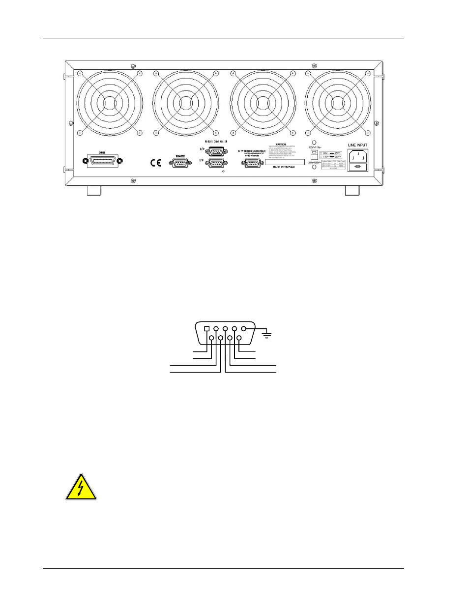
Sorensen SLM-4 Chassis
SLM
Figure 2–3 SLM-4 chassis Rear Panel
2.2.2 RS-232C
Connection
The RS-232C connector (female) on the rear panel connects the SLM-4 chassis to the
computer's RS-232C port.
2.2.3 Analog
Programming Input
The D-sub 9-pin connector on the rear panel connects the SLM-4 chassis to the SLM-Series
single input, the DC load module analog programming input, or to the external sync input of
SLM-Series AC load module. The pin connections are defined as shown in Figure 2–4.
CH1+
CH1-
CH2+
CH2-
CH4+
CH4-
CH3+
CH3-
1
5
Figure 2–4 Diagram of Analog Programming Input
2.3 MAINTENANCE
2.3.1 Cleaning
WARNING
:
To avoid electrical shock or damage to the meter, do not get water inside the
case.
Periodically wipe the case with a damp cloth and detergent; do not use abrasives or solvents.
2-4
M540069-01 Rev B
- CW-M (48 pages)
- CW-M Corrected Table 4-2 in (1 page)
- CW-P (62 pages)
- Lx Series (205 pages)
- CW Series Programming Manual (25 pages)
- Ls Series II Programming Manual (242 pages)
- Compact i/iX Series (157 pages)
- Compact IX 2253 (157 pages)
- Compact i/iX Series Software Manual (203 pages)
- ASD Series Quick Start (5 pages)
- ASD Series (120 pages)
- i-iX Series II Programming Manual (226 pages)
- DLM 600W Series Programming Manual (24 pages)
- M131 Programming Manual (99 pages)
- DLM Series (74 pages)
- DLM 600W Series (82 pages)
- BPS Series (153 pages)
- DLM600 Series (16 pages)
- DCS-E 1.2kW Series (65 pages)
- DLM-E 4kW Series Programming Manual (32 pages)
- M136 (8 pages)
- DCS-E 3kW Series (94 pages)
- CTS 3.0 (166 pages)
- CSW Series (174 pages)
- 2003RP (126 pages)
- 2001RP (131 pages)
- MX CTSH (151 pages)
- MXCTSL Administrator Manual (27 pages)
- MX CTSL (157 pages)
- RS Series (228 pages)
- MX Series Installation Manual (35 pages)
- Ls AC source (2 pages)
- MX15 Series (184 pages)
- Ls Series II (226 pages)
- Lx Series Driver Manual (275 pages)
- MX Series Rev: AY (257 pages)
- iX Series (341 pages)
- i-iX Series II (258 pages)
- GUPS 2400A-108 (36 pages)
- HPD Series (58 pages)
- HPD Series Operation Manual (41 pages)
- HPD Series GPIB-Multichannel (134 pages)
- PLA-PLW Programming Manual (74 pages)
- ReFlex Mating Connnectors for Controller (3 pages)
- LPDC-16V (4 pages)