0 adjusting simple antennas – Vectronics SWR-584B User Manual
Page 18
SWR-584B Instruction Manual
HF/VHF SWR Analyzer
18
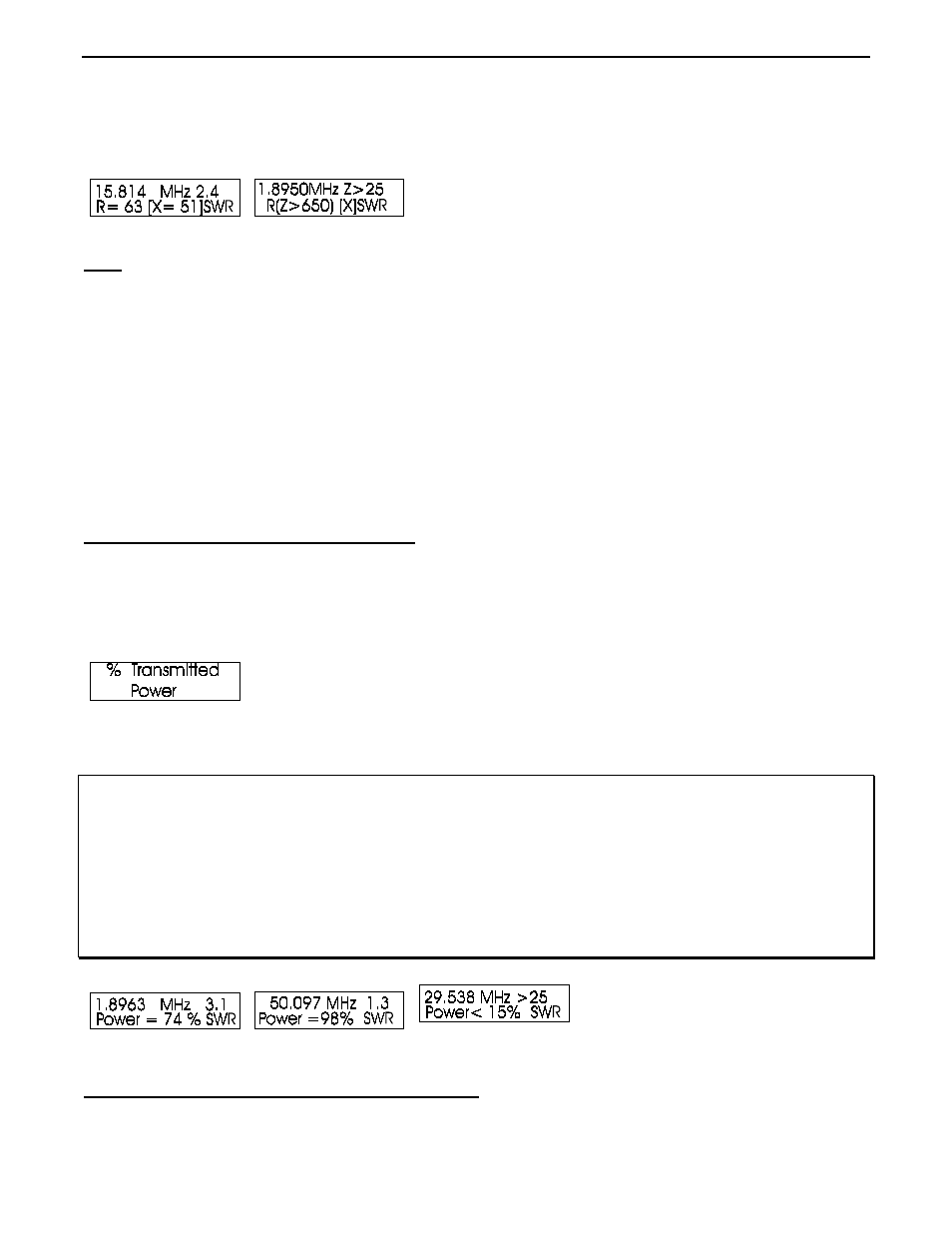
The Resonance Mode primarily draws attention to reactance, displaying reactance on the IMPEDANCE meter.
In this mode, the SWR-584B measures frequency, SWR, resistance (R= ), and reactance (X= ). When reactance
is zero, the system is said to be resonant.
Note: Zero reactance or resonance can occur on frequencies where the antenna is not actually
resonant. Conversely, the antenna may appear to contain reactance even at its true resonant
frequency when measured through a feedline.
A less than perfectly matched antenna and feedline, when used with a feedline that is not an exact multiple of 1/4
wavelength (0, 1/4, 1/2, 3/4, etc.), will have reactance added by the feedline. The added reactance may
coincidentally cancel the antenna’s reactance, making the system resonant. The SWR of the system, if the
feedline is a 50 ohm feedline with minimal loss and free from common mode currents, will not change as the
feedline length is changed. This is true even if the resonant frequency or reactance changes.
This mode functions like other SWR and impedance modes, with the exception the IMPEDANCE meter
measures reactance. This allows the operator to easily observe frequencies where system reactance crosses zero.
5.7
Percentage Transmitted Power
Percentage Transmitted Power mode is the final measurement mode available in the Advanced mode menu. This
mode is reached (after entering the Advanced mode menu) by pressing and releasing the MODE button four
times. It can also be reached (as all other advanced modes are) by stepping through advanced modes with the
MODE button until the display indicates “% Transmitted Power”.
Percentage of transmitted power is yet another way of describing SWR. It is similar to mismatch loss, but SWR
data is expressed as a “percentage of transmitted power”.
CAUTION: The name ‘‘% Transmitted Power’’ may mislead those unfamiliar
with SWR and energy transfer in a system. Power
‘‘transmitted’’ or transferred to a load can be nearly 100%
even if the ‘‘% Transmitted Power’’ display indicates a
system has nearly zero percent transmitted power.
Conversely, ‘‘% Transmitted Power’’ can be measured as
nearly 100%, and the actual transmitted power might be very
low.
6.0 ADJUSTING SIMPLE ANTENNAS