Vectronics SWR-584B User Manual
Page 12
SWR-584B Instruction Manual
HF/VHF SWR Analyzer
12
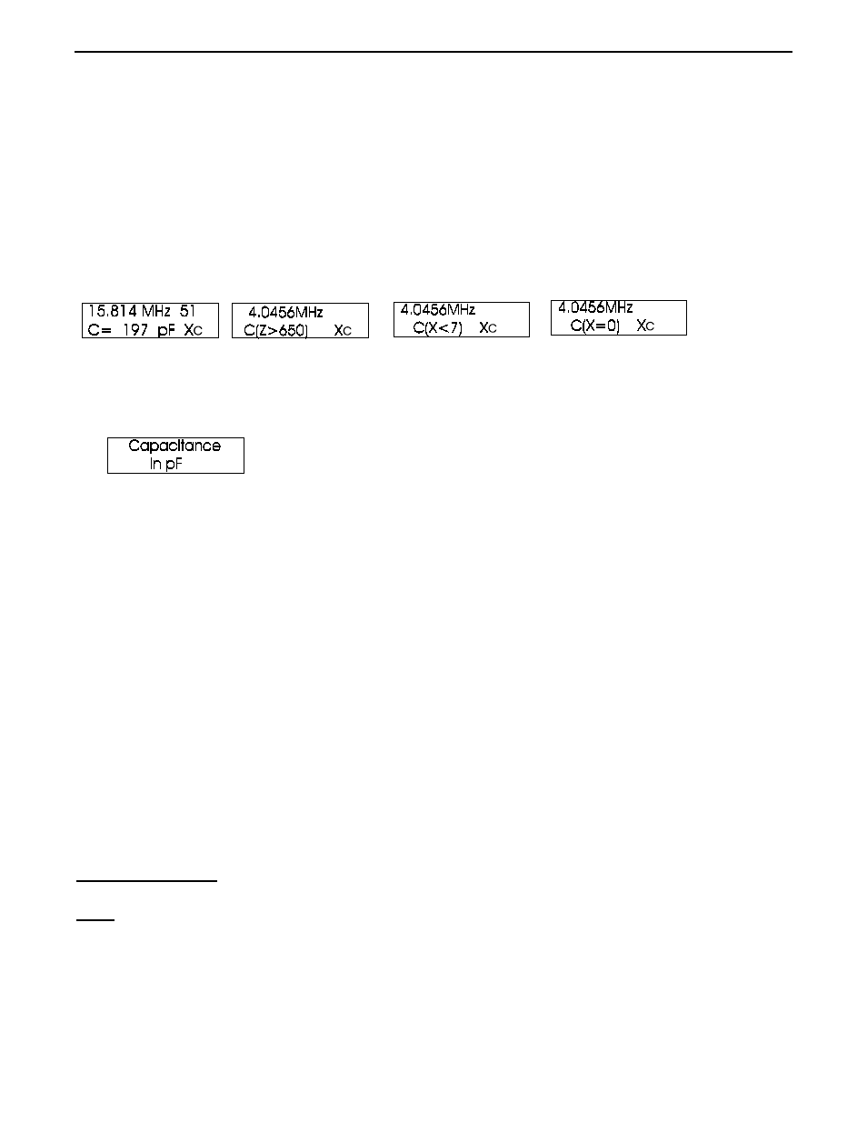
“Capacitance in pF” is the third mode. It measures capacitance values (in pF) at an adjustable frequency.
Normal measurement range is from a few pF to a few thousand pF. Capacitance is calculated using measured
reactance (X) and operating frequency.
The SWR-584B becomes inaccurate measuring reactances below 7 ohms or above 650 ohms. If the reactance of
the component is in the inaccurate range, “C(X<7) [X]” or “C(Z>650)” will be displayed. Capacitance values
will not be displayed if measurement accuracy is questionable.
To measure capacitance:
1.) Turn the SWR-584B on and step through with the mode switch until the “Capacitance in pf” display appears.
2.) Connect the capacitor across ANTENNA connector with the shortest leads possible, or with the lead length
normally used in the working circuit.
3.) Adjust the frequency to the closest frequency possible to the working frequency that does not produce a range
warning. C(Z>650) is one warning, and C(X<7) is another. C(X=0) indicates the capacitor appears as a near
perfect short to the SWR-584B.
When measuring a capacitor, the display value will likely change with test frequency. This happens because
stray inductance in the capacitor, and in wires to the “ANTENNA” connector, are in series with the capacitor.
Effective capacitance does change with frequency, and is often quite different from dc or low frequency ac
values. At higher frequencies the effective capacitance increases, reaching infinite capacitance when the
capacitor and stray inductance becomes series-resonant.
The frequency where the capacitor’s impedance, and the leads connecting to the capacitor, becomes (X=0) is the
series resonant frequency. Bypass capacitors are sometimes intentionally operated at or near the series or self
resonant frequency, but most applications are at frequencies far below the series resonant frequency.
The IMPEDANCE meter will indicate reactance (X in ohms) of the capacitor.
4.4 Inductance
Note:
The SWR-584B measures reactance, and converts reactance to inductance. The SWR-584B
can not determine if the reactance is actually inductive or capacitive. You can usually
determine the type of reactance by adjusting frequency. If frequency is increased and
reactance (X on the display or Impedance on the meter) decreases, the load is capacitive at the
measurement frequency. If frequency is reduced and reactance decreases, the load is
inductive at the measurement frequency.