Vectronics SWR-584B User Manual
Page 16
SWR-584B Instruction Manual
HF/VHF SWR Analyzer
16
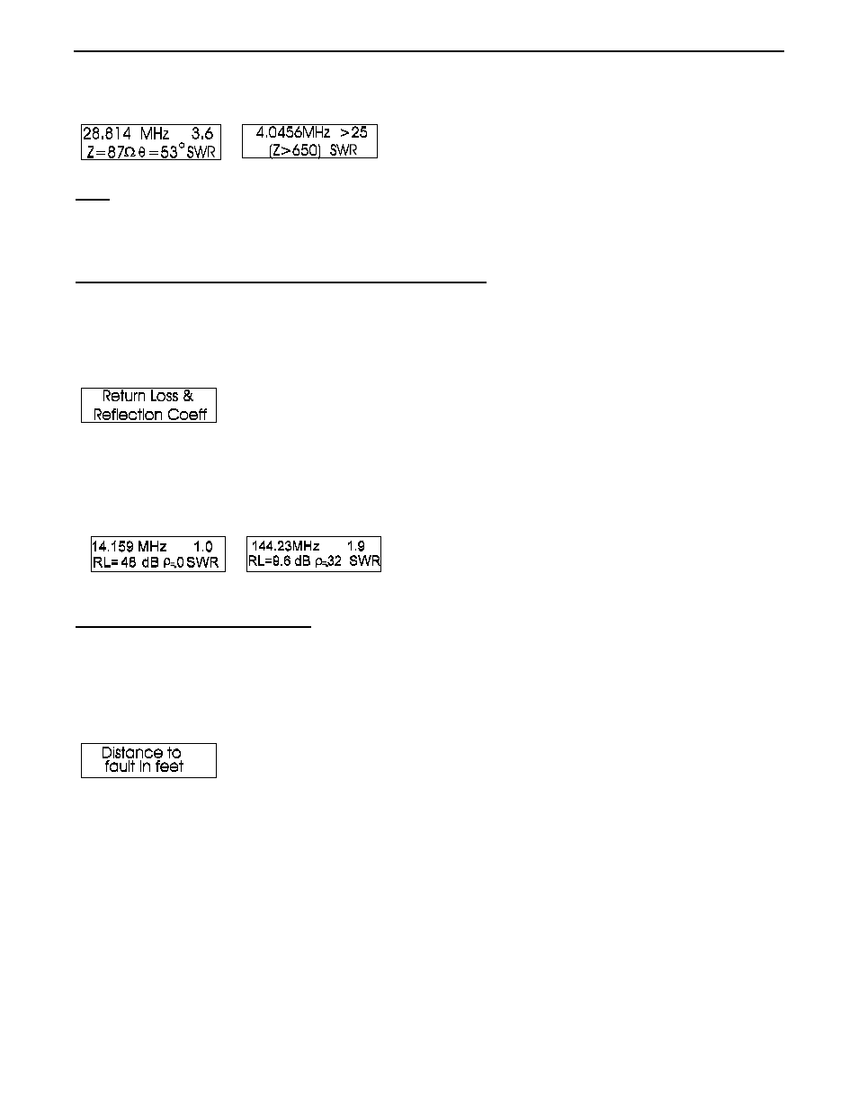
Note: Stray connector capacitance (4.4 pF) will be lower than 650 ohms at frequencies higher than 60
MHz. This small stray capacitance will not affect high frequency measurements, and produces
only minor errors in reading Impedances under a few hundred ohms at VHF.
5.4
Return Loss and Reflection Coefficient mode
The Return Loss and Reflection Coefficient mode is the second measurement mode in the Advanced mode menu.
This mode is reached by pressing and releasing the MODE button one time, after entering the Advanced mode
menu. You can also reach it, an all other modes, by stepping through Advanced modes with the MODE button
until the display indicates Return Loss and Reflection Coefficient.
The Return Loss and Reflection Coefficient mode measures and displays return loss in dB and voltage reflection
coefficient in percent on the LCD. The meters indicate SWR and impedance.
To use this mode, connect the load to be measured to the ANTENNA connector, adjust the frequency to the
desired frequency range, and read the results on the MFJ-259 LCD and panel meter displays.
5.5
Distance to Fault mode
The Distance to Fault mode is the third measurement mode in the Advanced mode menu. This mode is useful for
determining cable length, or distance to an open or shorted connection. This mode is reached by pressing and
releasing the MODE button two times, after entering the Advanced mode menu. It can also be reached (and all
other advanced modes) by stepping through Advanced modes with the MODE button until the display indicates
“Distance to Fault” (or other desired function).
If a balanced line is used, operate the SWR-584B only from internal batteries. Keep the SWR-584B a few feet
away from other conductors or earth, and do not attach any wires (other than the stub) to the unit. Use the
ANTENNA connector’s shield for one lead and its center pin for the other. Two wire balanced lines must be
suspended in a straight line a few feet away from metallic objects or ground.
Coaxial lines can lay in a pile or coil on the floor. Internal or external power can be used, and the SWR-584B
can be placed on or near large metallic objects with no ill effects. Coaxial lines connect normally, with the shield
grounded.
The Distance to Fault mode measures the electrical distance in feet to a transmission line fault or mistermination.
To obtain physical distance, multiply electrical distance by feedline velocity factor. If the distance is displayed