Vectronics SWR-584B User Manual
Page 11
SWR-584B Instruction Manual
HF/VHF SWR Analyzer
11
6.) If SWR changes with coaxial line length, line placement, or line grounding (any distance away from the
antenna) changes, the feedline has one or more of the following shortfalls:
a.) The feedline is carrying common mode current and radiating.
b.) The feedline is not a 50 ohm line.
c.) The feedline has high loss.
4.3 Coax
Loss
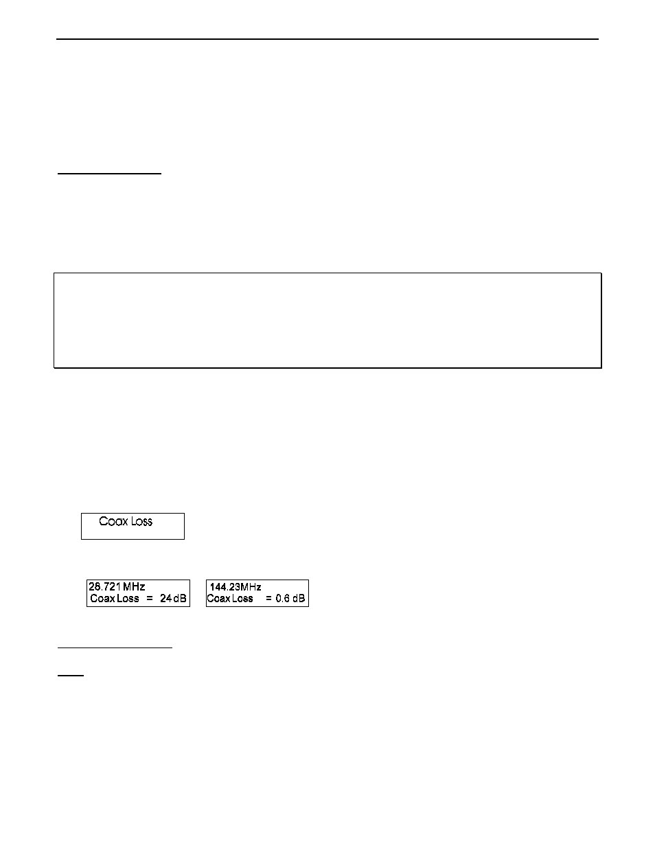
The second main (or opening) mode is “Coax Loss”. Access this mode by turning the SWR-584B on and
stepping to the Coax Loss display. In this mode, the SWR-584B LCD indicates frequency and coax loss in dB.
The meters are disabled. This mode was designed to measure 50 ohm cables, but measures differential mode loss
in many types of 50 ohm transmission line transformers and choke baluns, as well as loss in 50 ohm attenuator
pads.
CAUTION: Do not measure conventional transformers, or attenuators and
coaxial cables, with impedances other than 50 ohms. When
making measurements, the opposite end of the device under
test must have an open circuit, a short circuit, or a pure
reactance for termination. Any loss resistance will make
attenuation appear worse than it actually is.
To measure loss:
1.) Connect the SWR-584B to the 50 ohm cable, attenuator or transmission line type balun or transformer you
wish to measure. Be sure the distant end of the component you are testing is not terminated in any resistance.
2.) Turn the SWR-584B on. After the display reaches the opening measurement function, press the mode switch
once.
3.) The display should momentarily flash “Coax Loss”.
4.) Read the loss in dB at any frequency this unit covers.
4.4 Capacitance
Note: The SWR-584B measures reactance, and converts reactance to capacitance. The SWR-584B
can not determine if the reactance is actually inductive or capacitive. You can usually determine
the type of reactance by adjusting frequency. If frequency is increased and reactance (X on the
display or Impedance on the meter) decreases, the load is capacitive at the measurement
frequency. If frequency is reduced and reactance decreases, the load is inductive at the
measurement frequency.