Thor V3 Decoder - ASI, IP, RF - Closed Captions User Manual
Page 14
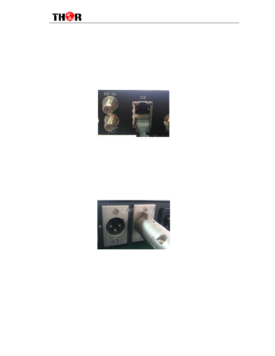
IP Output Connection Illustration:
Users can find the IP IN/OUTPUT
described on the rear panel illustration, and then connect the wire
connected to the IP input/output interface of the HD
connected to devices with IP OUT/INPUT a
XLR Output Connection Illustration:
Users can find the XLR interface on the device according to the connector mark described
on the rear panel illustration, and then connect the wire
the XLR output interface of the HD IRD,t
As follows:
10MHz IN &1PPSIN Connection Illustration:
You can find the 1PPS and 10MHz
mark described on the rear panel illustration, and then connect the wire
that the SFN solution is involved.
10MHz INinterfaces of the HD IRD,
follows:
H-HD-IRD
12
Connection Illustration:
interface on the device according to the connector mark
described on the rear panel illustration, and then connect the wire.One end of the wire is
output interface of the HD IRD,the other end of the wire is
OUT/INPUT as follows:
Connection Illustration:
interface on the device according to the connector mark described
on the rear panel illustration, and then connect the wire.One end of the wire is connected to
the XLR output interface of the HD IRD,the other end of the wire is connected to
PPSIN Connection Illustration:
Hz interfaces on the device according to the connector
mark described on the rear panel illustration, and then connect the wires on the c
that the SFN solution is involved.One end of the wireis connected to the 1
nterfaces of the HD IRD, and the other end of the wires is connected to
IRD-V3 User Manual
interface on the device according to the connector mark
One end of the wire is
other end of the wire is
interface on the device according to the connector mark described
One end of the wire is connected to
other end of the wire is connected toIP encoder.
on the device according to the connector
the ccondition
1PPS IN and
other end of the wires is connected toGPS as