Thor V3 Decoder - ASI, IP, RF - Closed Captions User Manual
Page 13
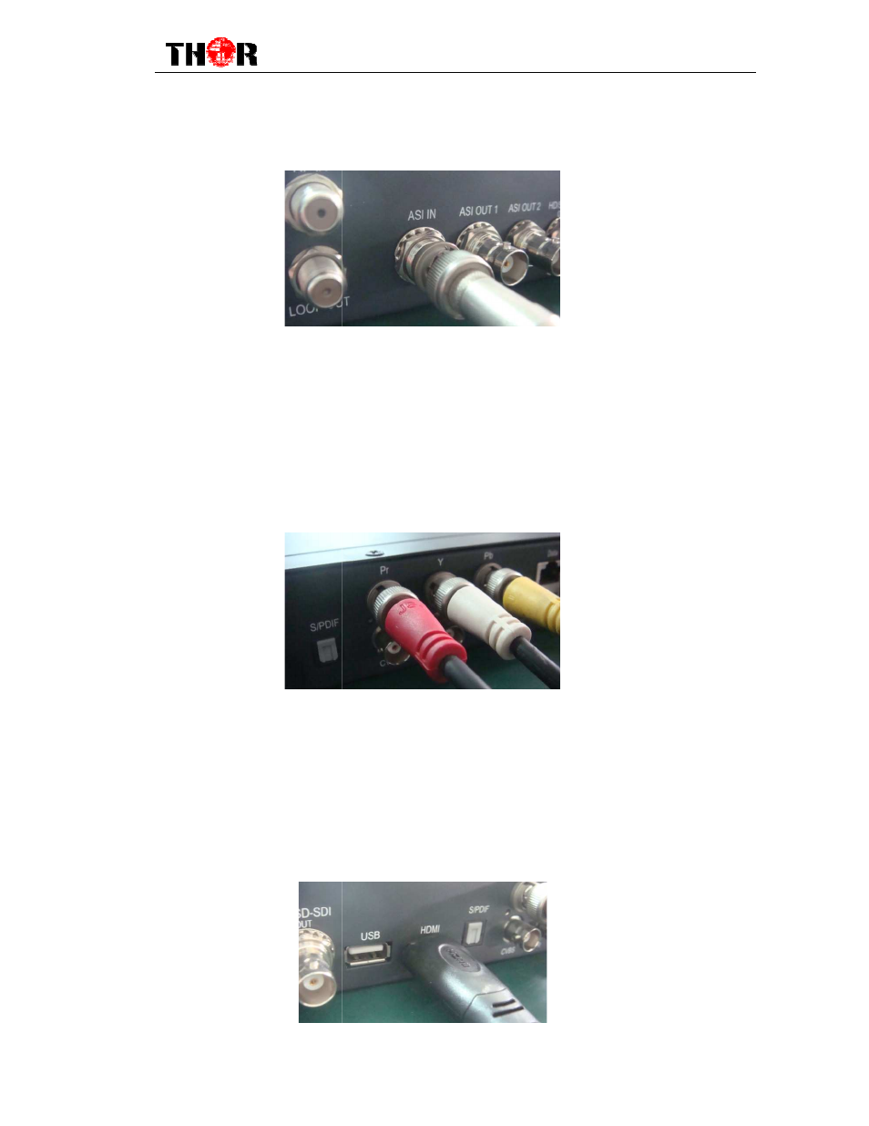
has ASI output, while when connected ASI OUT interface, the other end of the wire is
generally connected to encoder and
Component Output, CVBS Output and Sound Channel Output
Connection Illustration:
Users can find the YPbPr, CVBS and Left/Right soun
according to the connector mark described on the rear panel illustration
the cable. The other end of the wire is connected to encoders.
HDMI Output Connection Illustration:
Users can find the HDMI interface on the device according to the connector mark described
on the rear panel illustration, and then connect the wire.
to the HDMI output interface of the HD IRD, whilet
encoder or other equipment. As follows:
H-HD-IRD
11
when connected ASI OUT interface, the other end of the wire is
encoder and multiplexer. As follows:
CVBS Output and Sound Channel Output
Users can find the YPbPr, CVBS and Left/Right sound channel interface on the device
described on the rear panel illustration, and then connect
the cable. The other end of the wire is connected to encoders.
Connection Illustration:
interface on the device according to the connector mark described
on the rear panel illustration, and then connect the wire. One end of the wire is connected
the HD IRD, whilethe other end of the wire is connected to
. As follows:
IRD-V3 User Manual
when connected ASI OUT interface, the other end of the wire is
CVBS Output and Sound Channel Output
d channel interface on the device
, and then connect
interface on the device according to the connector mark described
One end of the wire is connected
he other end of the wire is connected to