H-4hdmi-atsc-ip – Thor 1-4 HDMI to ATSC Modulators 8VSB User Manual
Page 28
H-4HDMI-ATSC-IP
Figure-8
Modulator Setting
Enter in “Modulator” and it will display the Modulator Configuration screen as
Figure-9 where can set modulation parameters.
RF On –To enable the RF (carrier A/B/C/D) output or not.
RF Frequency A/B/C/D– to set the RF frequency for the 4 carriers
RF Out level –to set the RF output level
ASI Output– To select carrier output channel for ASI output (Output A: The ASI
output programs are same as carrier A; Output B: The ASI output programs are
same as carrier B; and the like.)
After setting all the parameters, click “Apply”
to save the Modulator
Configuration.
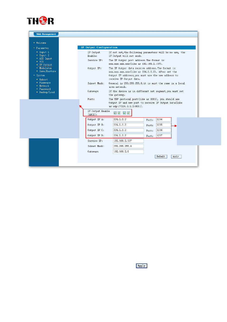
This device is has MPTS IP
outputs. The 4 boxes represent
respectively IP Channels 1/2/3/4.
Click the related box(es) to
enable
the
corresponding
channel(s) to output programs.
To configure the output
IP address and ports
for the 4 IP Channels
respectively.