H-4hdmi-atsc-ip – Thor 1-4 HDMI to ATSC Modulators 8VSB User Manual
Page 23
H-4HDMI-ATSC-IP
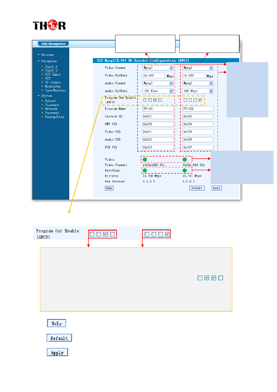
Figure-3
Enable or Disable the Carrier Output Function:
Further assistance if necessary
Click this button to apply the default setting of Input 1
Click this button to apply the modified parameters.
General
Settings for
the HDMI IN
programs:
User can edit
any item listed
as needed.
The 4 boxes respectively represent IP Channel A, B, C, and D. The related
programs can output through the selected IP Channel(s). (It shows that the 1
st
program outputs through IP Channel C and the 2
ed
through IP Channel D). One
program can also output through more than one IP Channels. (e.g.:
)
Refer to “1.4 Schematic Overview" for the relationship between the input
interfaces and encoder boards.
Click the box to enable or disable the program output through channel A/B/C/D.
Encoding Status—Green
light indicate it works
normally, which
otherwise turn to red.
This column is for setting
the 1
st
HDMI IN program.
This column is for setting
the 2
ed
HDMI IN program.