Anchor drive set-up (two speed models), Pengo revtrak manual 7, Figure 5d – Pengo RevTrak User Manual
Page 17: 6 4 figure 4d
PENGO RevTrak Manual 7
ANChOR DRIvE SET-UP (TwO SPEED MODELS)
NOTE: The following instruction steps are for PENGO RT series Drives only.
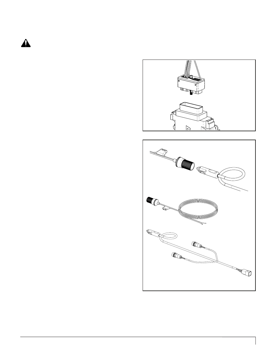
Connect wire harness (4) to controller (3). Align
the pins and complete the connection with a /4”
wrench. See figure 4D.
Note: Ensure that the wire harness connection is solid and
not binding or pinched.
5
Determine which cable (7 or 8) the 0’ or 20’ section
is necessary to sufficiently reach from the Drive to
the area in which the Display will be positioned.
Connect the Drive wire harness to the chosen cable.
Connect the other end of the cable to the Display wire
harness.
Note: Ensure that the cable has enough “slack” to allow
for full range or movement . Most cables can be run next
to the hydraulic hoses.
7
Arrange the cable connection end of the harness
in a way that will be easily accessible to connect to
the lead cables (7 and or 8). Suggested orientation
is to route the harness end through the top side of the bail
housing.
6
Figure 5D
TOLERANCES UNLESS OTHERWISE SPECIFIED
.X .1 [2.54 .XX .03 [.76] .XXX .010 [.25] ANGLE 1 DEG.
LBS
Kg
0.00
Figure 5B
THIS DRAWING IS THE PROPERTY OF PENGO 500 E.
HIGHWAY 10 LAURENS, IA. 50554. NO USE THEREOF SHALL
BE MADE OTHER THAN AS A REFERENCE FOR PROPOSALS
SUBMITTED BY PENGO CORPORATION AND/OR FOR JOBS
BEING EXECUTED IN CONFORMITY WITH SUCH PROPOSALS
HAVE BEEN ACCEPTED. UNLESS THE CONSENT OF SAID
PENGO CORPORATION HAS BEEN PREVIOUSLY OBTAINED.
NO PART OF THIS DRAWING SHALL BE COPPIED OR
DUPLICATED OR IT'S CONTENTS DISCLOSED.
DRAWN BY
MATERIAL
TITLE:
SIZE
REV
SCALE: 1:8
SHEET 1 OF 1
HEAT TREAT
THIRD ANGLE PROJECTION
B
DATE
CHECKED BY
TOLERANCES UNLESS OTHERWISE SPECIFIED
.X .1 [2.54 .XX .03 [.76] .XXX .010 [.25] ANGLE 1 DEG.
LBS
Kg
0.00
Figure 5B
THIS DRAWING IS THE PROPERTY OF PENGO 500 E.
HIGHWAY 10 LAURENS, IA. 50554. NO USE THEREOF SHALL
BE MADE OTHER THAN AS A REFERENCE FOR PROPOSALS
SUBMITTED BY PENGO CORPORATION AND/OR FOR JOBS
BEING EXECUTED IN CONFORMITY WITH SUCH PROPOSALS
HAVE BEEN ACCEPTED. UNLESS THE CONSENT OF SAID
PENGO CORPORATION HAS BEEN PREVIOUSLY OBTAINED.
NO PART OF THIS DRAWING SHALL BE COPPIED OR
DUPLICATED OR IT'S CONTENTS DISCLOSED.
DRAWN BY
MATERIAL
TITLE:
SIZE
REV
SCALE: 1:4
SHEET 1 OF 1
HEAT TREAT
THIRD ANGLE PROJECTION
B
DATE
CHECKED BY
4
6
This connection is only necessary
if an auxiliary power port is not
available. This is for battery
supplied power only.
6
4
Figure 4D
TOLERANCES UNLESS OTHERWISE SPECIFIED
.X .1 [2.54 .XX .03 [.76] .XXX .010 [.25] ANGLE 1 DEG.
LBS
Kg
0.00
Figure 4B
THIS DRAWING IS THE PROPERTY OF PENGO 500 E.
HIGHWAY 10 LAURENS, IA. 50554. NO USE THEREOF SHALL
BE MADE OTHER THAN AS A REFERENCE FOR PROPOSALS
SUBMITTED BY PENGO CORPORATION AND/OR FOR JOBS
BEING EXECUTED IN CONFORMITY WITH SUCH PROPOSALS
HAVE BEEN ACCEPTED. UNLESS THE CONSENT OF SAID
PENGO CORPORATION HAS BEEN PREVIOUSLY OBTAINED.
NO PART OF THIS DRAWING SHALL BE COPPIED OR
DUPLICATED OR IT'S CONTENTS DISCLOSED.
DRAWN BY
MATERIAL
TITLE:
SIZE
REV
SCALE: 1:8
SHEET 1 OF 1
HEAT TREAT
THIRD ANGLE PROJECTION
B
DATE
CHECKED BY
4
3
Complete connection by tightening
bolt. (/4” wrench)
The power source for the display will be determined
by the prime mover. It can be powered by an
auxiliary port commonly known as a “ cigarette light
port” or connected directly to the battery with the use of
the secondary power cord (6).
Battery Connection:
Connect the auxiliary plug on the display wire harness
(4) into the secondary power (6) cord once a battery
connection has been made. See figure 5D.
Note: Battery terminal ends are not provided on the
secondary power cord.
8