Anchor drive set-up (two speed models), 6 pengo revtrak manual, 64 b figure 3d – Pengo RevTrak User Manual
Page 16: Drawn by, Date checked by
6
PENGO RevTrak Manual
LBS
Kg
0.00
Figure 2D
THIS DRAWING IS THE PROPERTY OF PENGO 500 E.
HIGHWAY 10 LAURENS, IA. 50554. NO USE THEREOF SHALL
BE MADE OTHER THAN AS A REFERENCE FOR PROPOSALS
SUBMITTED BY PENGO CORPORATION AND/OR FOR JOBS
BEING EXECUTED IN CONFORMITY WITH SUCH PROPOSALS
HAVE BEEN ACCEPTED. UNLESS THE CONSENT OF SAID
PENGO CORPORATION HAS BEEN PREVIOUSLY OBTAINED.
NO PART OF THIS DRAWING SHALL BE COPIED OR
DUPLICATED OR IT'S CONTENTS DISCLOSED.
DRAWN BY
MATERIAL
TITLE:
SIZE
REV
SCALE: 1:4
SHEET 1 OF 1
HEAT TREAT
TOLERANCES UNLESS OTHERWISE SPECIFIED
.X .1 [2.54 .XX .03 [.76] .XXX .010 [.25] ANGLE 1 DEG.
THIRD ANGLE PROJECTION
C
DATE
CHECKED BY
C
Figure 2D
REV
NOTE: The following instruction steps are for PENGO RT series Drives only.
ANChOR DRIvE SET-UP (TwO SPEED MODELS)
Remove bail housing to expose hydraulic motor.
Note: before removing the bail housing scribe a line from the housing to the gearbox to indicate a reference mark
for re-assembly.
1
Figure D
Figure 2D
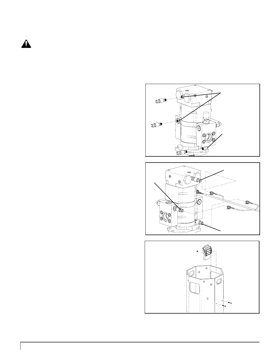
Remove three threaded plugs from the hydraulic
motor to install the transducers (6):
. Remove the plug from the elbow located on the
pressure side of the hydraulic block.
2. Remove the plug from the tank side of the hydraulic
block.
3. Remove the plug from the sequence port located near
the top of the motor. See figure 1D.
Once the plugs have been removed install three pressure
transducers (6) in the three exposed ports as shown.
Note: use of Teflon tape on the threads of the transducers
is highly recommended to reduce potential leaks.
2
Secure wire harness (4) to the transducers (6).
. Clip harness end marked “
Pressure” to the
pressure side transducer.
2. Clip harness end marked “
Tank” to the tank side
transducer.
3. Clip harness end marked “
Sequence” to the pressure
transducer located near the top of the motor.
See figure 2D.
3
Fasten controller (3) to the bail housing as shown
in figure 3D with bolts (17) and nuts (18). The bail
housing will have existing holes typically located
on the front face of the housing.
4
TOLERANCES UNLESS OTHERWISE SPECIFIED
.X .1 [2.54 .XX .03 [.76] .XXX .010 [.25] ANGLE 1 DEG.
LBS
Kg
0.00
Figure 1D
THIS DRAWING IS THE PROPERTY OF PENGO 500 E.
HIGHWAY 10 LAURENS, IA. 50554. NO USE THEREOF SHALL
BE MADE OTHER THAN AS A REFERENCE FOR PROPOSALS
SUBMITTED BY PENGO CORPORATION AND/OR FOR JOBS
BEING EXECUTED IN CONFORMITY WITH SUCH PROPOSALS
HAVE BEEN ACCEPTED. UNLESS THE CONSENT OF SAID
PENGO CORPORATION HAS BEEN PREVIOUSLY OBTAINED.
NO PART OF THIS DRAWING SHALL BE COPPIED OR
DUPLICATED OR IT'S CONTENTS DISCLOSED.
DRAWN BY
MATERIAL
TITLE:
SIZE
REV
SCALE: 1:1
SHEET 1 OF 1
HEAT TREAT
THIRD ANGLE PROJECTION
B
DATE
CHECKED BY
Elbow located under
Pressure Block
6
6
6
4
B
Figure 3D
TOLERANCES UNLESS OTHERWISE SPECIFIED
.X .1 [2.54 .XX .03 [.76] .XXX .010 [.25] ANGLE 1 DEG.
LBS
Kg
0.00
Figure 3C
THIS DRAWING IS THE PROPERTY OF PENGO 500 E.
HIGHWAY 10 LAURENS, IA. 50554. NO USE THEREOF SHALL
BE MADE OTHER THAN AS A REFERENCE FOR PROPOSALS
SUBMITTED BY PENGO CORPORATION AND/OR FOR JOBS
BEING EXECUTED IN CONFORMITY WITH SUCH PROPOSALS
HAVE BEEN ACCEPTED. UNLESS THE CONSENT OF SAID
PENGO CORPORATION HAS BEEN PREVIOUSLY OBTAINED.
NO PART OF THIS DRAWING SHALL BE COPPIED OR
DUPLICATED OR IT'S CONTENTS DISCLOSED.
DRAWN BY
MATERIAL
TITLE:
SIZE
REV
SCALE: 1:1
SHEET 1 OF 1
HEAT TREAT
THIRD ANGLE PROJECTION
B
DATE
CHECKED BY
3
7
8
Pressure
Tank
Sequence
Note:
Do not remove the entire
port plug. Only remove the
small threaded plug from
the middle.