Paxton Superchargers 4.6L SOHC Mustang GT User Manual
Page 23
P/N: 4809655
©2007 Paxton Automotive
All Rights Reserved, Intl. Copr. Secured
16AUG07 v1.0 96-03MusGT(4809655v1.0)
4-3
C.
Attach the supplied K & N air filter, 3-1/2"
sleeve, 90° x 3-1/2" elbow and #56 hose
clamps to the MAF and secure.
*** NOTE ***
1996-2001 models use the 90° x 3-1/2" plastic inlet
elbow with the hole and grommet in the side. 2002+
models use the 90° x 3-1/2" plastic elbow without a
hole in the side. Both elbows have been supplied.
D.
(1996-2001 Models only.) Insert the factory
air temperature sensor into the rubber grom-
met located on the side of the 90° elbow.
Lubricate for easier fit. (See Fig. 4.2-a.)
*** NOTE ***
2002-2003 models do not have a separate IAT
sensor.
E.
From beneath the vehicle, remove the two
factory nuts and washers from the passenger’s
side lower fender valence. Mount the
MAF/bracket assembly onto the existing studs
using the same washers and nuts originally
removed.
F.
Using a #52 hose clamp, connect the piece of
3-1/2" flex hose to the elbow attached to the
MAF meter and route it through the opening
in the right side inner fender toward the
supercharger. Make sure the 3-1/2" flex hose
does not contact or rub on the edge of the
inner fender opening. (Eventual hose failure
will result if the hose is not properly routed.)
G.
Route the factory temperature sensor and
MAF sensor connectors out through the inner
fender opening. Reattach the connectors to the
relocated sensors.
H.
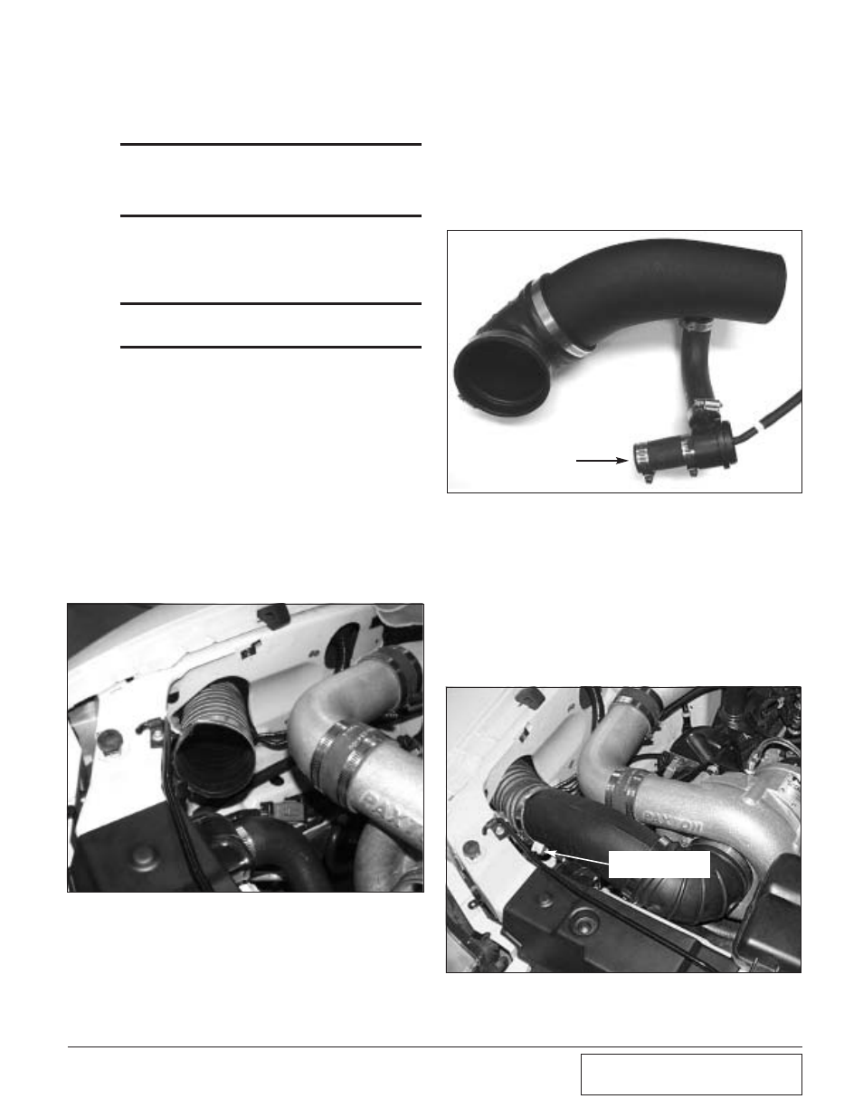
Install the bypass valve assembly on the
underside of the secondary intake tube. (See
Fig. 4.2-c.) (See Appendix “J” for bypass
assembly procedure.)
Fig. 4.2-b
Fig. 4.2-c
ATTACH TO
DISCHARGE DUCT
I.
Place the secondary intake tube/bypass valve
assembly on the supercharger inlet and attach
it to the flex hose. Attach the other end of the
bypass valve to the discharge tube. Connect
the hose that was previously installed on the
hard plastic crank case ventilation line to the
brass fitting on the intake tube. Tighten the
clamps. The finished installation appears as
shown. (See Fig 4.2-d.)
Fig. 4.2-d
BRASS FITTING TO
VALVE COVER VENT