Step 3 linking multiple units, Step 4 operation – Dan Dugan Sound Design E User Manual
Page 11
Dugan Model E User Guide
Quickstart
11
Step 3 Linking Multiple Units
All linked units must be in analog audio I/O mode and use analog connections to the
board because linking requires the digital I/O connectors. Up to eight Model Es (64
channels) can be linked into a single system that maintains the gain of one mic from the
room no matter how many mics are connected. One unit must be the master and the oth-
ers slaves.
Set the
NORM-SLAVE
switch on the rear panel to
NORM
(up) to designate that Model
E as the Master. Set the
NORM-SLAVE
switch on the rear panel to
SLAVE
(down) to
designate that Model E as Slave.
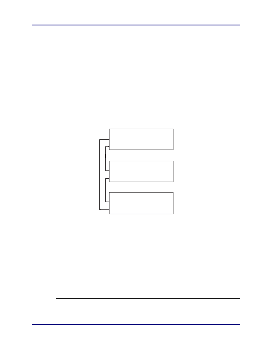
Link units in a ring configuration as shown below. Note that all
LINK IN
and
OUT
con-
nectors are used to create the ring.
Figure 2-3 Linking units
Step 4 Operation
Raise your console preamp gains until the Model E’s green
level
LEDs stay illuminated
when the room is quiet. The
level
LED illuminates green when the input level is within
the acceptable range for automatic mixing and flashes red to indicate clipping. There
should be enough gain ahead of the Model E to maintain the green LED at all times.
NOTE: When the green light goes out, the channel is in a downward expansion mode
to avoid feedback. This condition should be avoided because the smooth am-
bience characteristic of Dugan automatic mic mixing is lost.
OPTICAL LINK
OPTICAL LINK
IN
IN
IN
OUT
OUT
OUT
Master
OPTICAL LINK
Slave
Slave