Fig. 5, Fig. 5:1 the motor, Fig. 5:2 s – Crompton Controls M20 User Manual
Page 17: Fig. 5:3, 3, Ctm025
16
Selection of Current Transformer
Emotron AB 01-2551-01r4
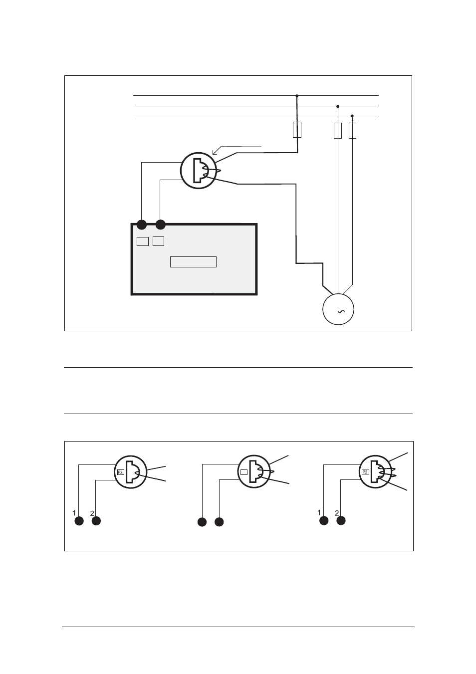
Fig. 4
Example CTM 025 with 2 windings for a 12 A motor
Fig. 5
Example 1, 2 and 3 windings.
NOTE: The current transformer connection and orientation are not polarity
sensitive, but must be connected to the same phase that is being
referenced for terminal 9 of the M20.
L1
L2
L3
1
2
S1 S2
M
3
M20
2 windings
CTM025
P2
1
2
P2
5:1
5:2
5:3